Categories
Part Review

New Project — ChipReport.TV

So I’ve continued to keep myself busy lately. I have a new project called ChipReport.tv. I’ll be reviewing the newest released parts so you don’t have to work so hard to find them.

Here’s the intro video:

And here’s the first installment!

Around here, I hope to do a site refresh soon, since this blog has gotten a little stale. I think I’d like to transition it to more of a traditional “home page” for all the things I’m working on. Comments welcome on any of the above.

Categories
Part Review

Part Review: LT4180

A note about part reviews: I do not get paid to do reviews. I am either doing them out of the kindness of my heart, because they have some historical significance (as in the case of my review of the LM741) or most likely I think the technology is important and interesting. All opinions are my own and I would not suggest making any part choices based on the information in this article alone. Read some datasheets, they’re pretty informative.

No wire is perfect.

Basically, that’s the premise behind this chip, the LT4180. The real background is that when someone is providing power to a remote device they want the voltage to be accurate.

An example of this might be a USB supply to a device more than 20 feet away. The host (whatever is in charge of setting up communication and providing power, such as a computer) is supposed to supply 5V to the device (such as a printer or a mouse). In this case let’s assume that the device is very dependent on that voltage being correct, for one reason or another. The real problem is that the wire providing that power has some innate resistance to it.  Even a resistance of 1 ohm at 500 mA (the max current of USB) can cause a drop of .5V. That’s 10% of the intended voltage!

So what are the traditional options? Well, the best one is to have a separate set of wires known as “sense” wires. They detect the voltage directly at the device without drawing much current (likely by utilizing high input impedance op amps).  So the current that is powering the remote device will be sourced through one set of wires and the voltage at the device will be fed back to the whatever is supplying the voltage. In theory if the resistance of the wire changes (due to temperature, stress, etc), the controller will react and adjust the voltage up or down so the correct voltage is delivered to the device.

But what if you already ran your wires and you can’t run a second set to sense the remote voltage? You either design in a regulator on the device side (a good idea regardless) and source a higher voltage or you just design in devices that can handle a large swing of voltages. Neither is the best idea, though they are likely to be cheaper than using this part. At $3 minimum price you’re much more likely to find a cheapo linear regulator which you can put on the device end and then burn power there. You lose efficiency but gain a few points with the MBAs in your company.

Enter the LT4180. You can put this device in line with a voltage regulator, as shown on page 6 of this wonderful app note.

As a quick aside, you know LT cares about this product as Bob Dobkin, the co-founder and Chief Technology Officer at Linear, co-wrote the app note. Very cool, you don’t see high level execs getting their hands in on the action very often these days.  I was impressed at least.

Back to the app note itself, you’ll see that there is a switching regulator or linear regulator that is providing the initial voltage. Then this device sits between the voltage regulator and the wires that lead out to the device. Notice also that there are only two wires, a source wire and a return wire.

Now for the magic. It has two key pieces, explained in better detail in the app note, but summarized here.

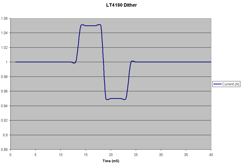
The Dither — LT calls it an algorithm, but in effect they are only stepping the supply current up and down by 5%. So if the initial regulated current is 1A, they step it up to 1.05 A and then down to .95 A (similar to what is shown below with a different timescale). Why? Because it’s effectively forcing an AC (varying waveform) through what was a DC (non-varying) channel.

Doing so allows you to gather the impedance of the channel without directly measuring the drop due to the resistance in the wires that are sourcing current. According to the app note:

Because C is sized to produce an “AC short” at the square wave frequency, the interrogating voltage square wave produced at the power supply is equal to VSUPPLY(AC) = 0.1 × IDC × R, measured in Vpp. The voltage square wave measured at the power supply has a peak-to-peak amplitude equal to one tenth the DC wiring drop. This is not an estimate—it is a direct measurement of the voltage drop across the wiring over all load currents.

As illustrated below, the AC square wave is now shunted to ground instead of going to the load. This is how you can be certain it’s the actual resistance of the channel and not the channel AND the load. How cool is that?

The Control — Wait a second, how do they do that when they are not a part of the switching regulator or linear regulator? Nor does the regulator have any control lines with SPI or I2C or similar? LT illustrates 2 ways, but the basic idea is the LT4180 feeds back an analog voltage to the controller. This can then be used in myriad ways. The most straightforward way is to feed this voltage back to an error amplifier on the regulator, if it has one. The error amp will interpret any incoming signal as an error and correct the output. By dithering this signal by a little in either direction, the output current from the regulator can be made to vary. Other methods shown include feeding the signal into the trim circuitry (that controls the precise voltage allowed by certain regulators) or even feeding it into a discrete MOSFET based current source. With the voltage feedback signal there are certainly a lot of creative ways to feed this information back to your regulator/switcher to achieve the desired dither.

All in all, I was impressed by this part. I haven’t had it on my bench yet to try it out, but the idea alone made it intriguing enough to write about. Power is a really big market and growing and Linear Tech makes no secret of the fact that they are targeting the more obscure but lucrative problems such as this one.  I’d like to reiterate that the app note is fantastic for this part and the datasheet fills in technical details and specifications that aren’t in the app note. Hopefully I made what was already well written a little easier for others to comprehend on the first pass.

For people that have landed on this page from Google, I would prefer that you do not ask any design questions, I am not actively using this part and I’m sure there are many others out there that would serve you better. For everyone else, if you have any questions, please leave them in the comments. Thanks for reading!

Categories
Part Review

Part Review: LM741

We all have to start somewhere.

I’ve been thinking about my posts as of late. Moreso, how I can offer something of substance to readers. At least substance that is usable on a daily basis. What do EEs want to read when they get to this site?

I came up with part reviews. I started something similar at my other project, Electricio.us. Spec sheet analysis is a critical skill for any analog engineer. It’s also is time consuming and hard to keep up with. So why not have a few choice parts highlighted on here? I don’t plan on reviewing the newest and hottest parts…but maybe the most useful. So let’s start with the LM741.

a uA741 op amp in action on a breadboard

A 741? These are parts I joke about, not parts I use on an everyday basis. But like I said, we all have to start somewhere. I’m sure many of us started using this part in electronics labs and at home in hobby projects. It’s the quintessential beginner op amp and it was one of the first ever designed.

LM741 datasheet from National Semiconductor

Pros:

  • Cheap — Being made by multiple vendors (necessarily called the LM741 but probably containing the number 741 somewhere in the title) really can help with cost.
  • Standard pinout — Sometimes even more valuable than having something cheap in the first place, being able to find a drop-in replacement can be a godsend when in a bind. This has been doubly true with the economic downturn. Sure, the part being out for 42 years doesn’t hurt either. People managed to figure out it’s pretty popular since it first arrived on the scene and duplicated this trailblazing part’s pin assignments.
  • Nulling circuit — As we’ll see in the “cons” about this part, the offset voltage is horrible, but the tuneability of the part is a nice feature if you have to use this part. The “offset null” pins give you access to the 1K emitter resistor circuit, basically allowing you to drive the input voltage on one side of the op amp higher by giving a different resistance for the bias current on the input stage. This effectively raises the voltage on one side of the input or the other (inverting or non-inverting). Pretty neat stuff!
  • Bandwidth — For an old part, the bandwidth on the 741 is 1.5 MHz. This is set by the internal capacitor, which acts as a pole inside the circuit and limits how fast the circuit can respond. This is extra interesting because the 741 was the first part to ever do this inside of the IC itself; previously you had to set the compensation capacitor externally. At 1.5 MHz, this old geezer of a part can still get up and move like a jackrabbit.

Cons:

  • Offset voltage — As you can see above, the nulling circuit is necessary because the offset voltages can get pretty extreme on the inputs of this op amp. “So what?” you say. Well, this causes issues when any kind of precision is required. If you put in a 1 volt signal into an LM741 that is set up in a buffer configuration, the 5 or so mV of offset voltage between the inputs will get passed directly to the output! That’s .5% of your signal right off the bat! And if there is any gain in the circuit (i.e. it being set up in an inverting or non-inverting configuration), then your offset gets multiplied by whichever gain you apply to the circuit! That means for a gain of 10, your 1V input signal now has an output offset of 50 mV! Say goodbye to DC accuracy!
  • Offset voltage drift –Even if you decide to “dial in” an offset null resistance on the proper pins, this is only accurate at the temperature you were at while correcting the offset. For every degree change, there is another 15 uV of voltage offset.
  • Bias current — We all know that in an ideal model of an op amp, you assume there is no current flowing into the inputs terminals. Well, that’s never really the case, and having any current flowing into the terminals can cause DC offsets once that current flows through resistors (such as in a non-inverting amplifier configuration). The standard bias current spec’d on this part is .1 to 1 uA. That’s nothing to write home about, especially if you care about DC accuracy. The downer on this poor spec is that there isn’t an internal “knob” to help with the bias current; you just have to deal with it and try to design around it.
  • PSRR — Though it’s not the worst I’ve ever seen, the PSRR on this part isn’t great either. At a typical value of 77 dB (use 80 for easy math) that means that any noise appearing on the power rails will show up 10^-(80/4) times on the output. So if you see a 1V transient on a 15V supply rail (gah! huge!), then you will have a 10 mV spike on the output. This can cause some serious noise problems down the line and most op amps I’ve been looking at these days have been well north of 100 dB PSRR.

This part is old, no way to overlook that. But it is still relevant part and is the basis for many parts that exist today. That’s pretty impressive some 40 years later. The downsides show the part’s age but are a symptom of the technology and the time this part was developed. The transistors are BJT, compared to the MOSFET based parts of today; many of the specs are guaranteed to be worse on this fact alone (though not the speed nor the power handling ability).

If you have a simple need for an op amp and you know how to properly account for all the shortcomings in this op amp, it’s a fine choice. Like I said above, it’s low cost, easy to use and plentiful in supply. And if history has shown anything, it’s that this part is not going away anytime soon.

So this was my first part review. I think in the future instead of running down the list of a lot of the specs like I did here, I would focus instead on one or two of the spectacular properties of a chip or the extremely underwhelming properties of a chip. Comparing all the middle of the road specs is a waste of everyone’s time. I wanted to make sure I covered a few things here as a baseline for future reviews though. I’d also like to step outside the bread and butter parts of an analog electrical engineer’s part drawer (the op amp) and review other types of components.

If you have any you would like to see reviewed in the future or have any thoughts about this review, be sure to leave a note in the comments.

Thanks to 畢業了吧 for the photo