I’m working on a new switcher design and need to be able to test the total current coming out of a boost converter. Here’s what I’m looking at:
- 0-60V rails (out of the boost converter)
- 0-350 mA
- No access to the load that will eventually be connected to the switcher
So what do I need? I need something that can sink current and dissipate any heat that will be generated. If the load is dropping the entire voltage at the top current, that will be:
$$!60V * .350 A = 21W$$
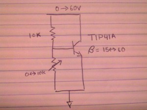
This is quite a bit of power. I was using the TIP41A that I have on hand, a power NPN transistor in a TO-220 package. With this amount of power, a heatsink is most definitely required. Here’s the simple circuit:
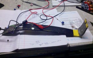
In this circuit, the divider from the incoming source (the top rail) sets the current going to the base ($$i_{B}$$) and this times the $$beta$$ (in this case anywhere from 15-60) equals the current down through the collector ($$i_{C}$$). This is not the optimal way to sink current from your source, but it’s a start. The fact that I’m dialing in the current with a potentiometer in a divider that is also connected to the incoming load is not great, but again, this was a quick and dirty way to get up and running. But wait, you think that’s a makeshift circuit? Check out my heatsink:
Yup, that’s a crowbar.
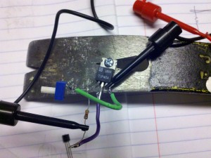
Close up of the attached BJT
I didn’t have any proper heatsinks laying around, so this became my hacked version. During testing, I was looking at 30V across the TIP41A and roughly 300 mA through it. The heat was transferred well from the TO-220 case to the crowbar and the dissipation was decent (heatsinks with fins are better at dissipating the heat). Next I need to step it up and see if this simple circuit can perform under full load. If there was perfect contact between the case and the crowbar, we should see roughly:
$$!Power * R_{theta_{j}} = Delta ^{circ}C$$
$$!21W * 1.92 ^{circ}C/W = 40.32 ^{circ}C$$
I wouldn’t be putting my tongue on the crowbar anytime soon, but I think that’s reasonable enough to handle this situation.
Now, there are much better ways to do this. I really like my co-host at The Amp Hour, Dave Jones’ video about a programmable dummy load. Hell, he even has a legit heatsink! There are advantages to using a MOSFET over a BJT as well, but I went with a BJT for this situation. Mostly I was just giggly about using a crowbar and thought others might enjoy. So…hope you enjoyed! If not, check out Dave’s video below:


10 replies on “Makeshift Current Sink”
How does crowbar stack up to a aluminum beer can as heat sink? Crowbar has greater cross section but aluminum has less thermal resistance.
Haven’t ever tried a can but from a total mass perspective, the crowbar wins. It can sink much more total heat, though you’re correct that a piece of aluminum the same size would be able to get rid of it faster.
I love it! Kinda like when I slapped together my treadmill desk (and have been getting spam trying to get me to buy a new one ever since).
Nice! I created similar makesift current sink when i needed to test a failing PSU how it would handle under 10A load. I used IRFP064 mosfet and old cylinder block form Suzuki pv50 from my younger days. Only pot i had lying around was 1 turn 10K stereopot so adjustment was a bit touchy. 120W was max i had balls to try because the only feedback was 8$ multimeter that had limit of 10A. http://jkphoto.pp.fi/upload/pv50.jpg
Hey, *that* what I call crowbar protection! Beats my wimpy SCR-based efforts! B^>
Rgds
Damon
[…] And while a crowbar is not on the list, Chris keeps one around his lab for a heatsink… […]
Haha nice. Clearly a crowbar is the tool I am missing, just so I could do this kind of thing.
A little thermal grease will do wonders.
Chris, I bet it would work -really- well if you put one end of the crowbar in some ice water.
[…] don’t have a screw hole to attach a large heat sink, like a Gammell Crowbar. And even if there was it would need to fit in the housing. So I worked solutions with what I […]