Categories
Analog Electronics Conferences

Improve your circuit toolbox – Simple designs that will save your next product

I had the honor of speaking at the 2018 Hackaday Superconference over the weekend. It is one of my favorite conferences of the year. The engineers and makers I met there are focused on using their creative energy to make the world a more interesting and better place. I posted a preview of this talk in my “Humble Indicator LED” post earlier this year. This later morphed into the talk shown below. It’s about circuit designs that I have found or used in my life to save products. Watch the talk here:

Corrections (of course):

  • 7:10: The LED schematic for the on/off indicator was copied without testing. A working version is here.
  • 23:30: In the course of being cheeky I call it an instrumentation amp (wrong), but later correctly call it a differential amplifier.

Many people have been asking for the slides, I have them here:

Download the pdf of these slides here

Looking to get in touch with me about these slides, my course, the podcast or hiring me to work on an electronics design? Check out the contact page.

I’ve turned off the comments for this post, as I’d love to discuss this over on the Contextual Electronics forum. Please stop by and let me know what you think!

Categories
Analog Electronics

The humble indicator LED

I proposed a talk to the Hackaday Superconference yesterday titled,  “Improve your circuit toolbox: Simple designs that will save your next product”.

While I don’t know if the talk will be accepted, I thought it could be a good discussion regardless and thought I could write out some thoughts here. I haven’t been writing much lately and wanted to stretch my muscles again, so why not?

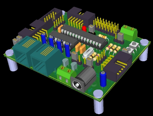
The first circuit on that list will be an indicator LED.

Yep, that simple of a circuit. Allow me to share a diagram:

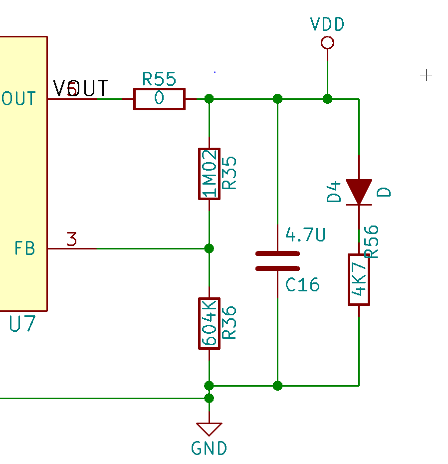
The power of the blink

All this circuit does is light up. When the user inserts batteries and enables the circuit via a physical switch, the power flows through the regulator and lights up D4 which is a red LED. That’s it.

The crazy thing about this circuit? The LED indicator was not implement until rev 3 of the design! Prior to implementing this I only knew the status of the board when I put a DMM across the power terminals.

Throughout the testing of the above project and in many other projects, I have shorted things out by accident. When there is a power indicator LED on board that starts to blink because I’m dragging down the power rail, it’s easier to stop doing what I’m doing. If that isn’t there, sometimes the only indicator is another part of the circuit communicating intermittently or the switching converter starting to whine.

The serial blink

Arduino users will know this one well, there are LEDs that are attached to the serial lines. When you’re programming the board or transmitting back via the serial console, the indication is obvious.

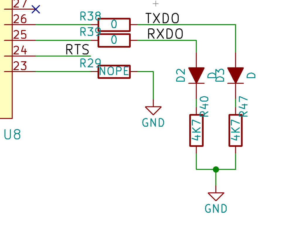
You need to be careful with your serial lines, ensuring your LEDs don’t pull too hard on the lines. Set your current with the proper sized resistors so you don’t mess up the edges of your serial lines. When in doubt, take them out.

Blink is optional

You don’t need to end up populating these parts when you go to production. Your low power product might not be able to spare the milliamps of current. You can either “turn down” the resistor brightness by using a higher value resistor or you can leave the LED out entirely when you’re certain you have a stable product.

Your eyes are test equipment

While these circuits are super simple, it effectively re-purposes your eyes as test equipment. There is a high amount of light sensitivity in the human eye and even small changes like brightness difference or flicker will showcase that “something is different” if not “something is wrong”.

LED indicators will help you troubleshoot your next product. Be sure to add them to any/all of the following:

  • Input power
  • Output power – After your custom regulation
  • Output power – After regulation happening on a chip or module
  • USB power (if separate from your input power)
  • Battery charging
  • Serial lines
  • Status LEDs
Categories
Analog Electronics Digital Electronics Work

As big as…space

Last week on my electronics podcast, The Amp Hour, I did something uncharacteristic: I mentioned where I’m working, while I’m working there. Normally I don’t talk about my place of employment until after I have left, which has always served me well. There is no conflict of interest in talking about work that protected by non-disclosure agreements (NDAs).  This time is different though, because the nature of the company is different (and my role will be more public facing than my normal role as an engineer).

I’ve been working with Supply Frame part time, in addition to my work on Contextual Electronics. It has been great working with a team dedicated to making the supply chain (the complex system of vendors and distributors) a bit easier to navigate. As it so happens, Supply Frame also purchased a popular blog site a while back that I have always been a fan of, Hackaday. That site highlights fun projects from around the web and is a great way to keep up on recent innovations in personal projects.

So why all this explaining and build-up? Well I’ve also been asked to help out on a project as part of Hackaday. In fact, it falls in line with my past experience of running the 555 contest back in 2011.

Hackaday is sending the grand prize winner of a new design contest to space. Whoa.

When they first told me about this idea, I figured they must be joking. How the hell would this be possible? Well, it turns out there are more and more commercial space flight options opening up. These days with enough money (and yeah, it’s a lot of money), you can buy a ticket to ride. So that’s how we’re doing it.

The contest itself is really exciting as well. The goal is for people to build “open, connected hardware”. In my experience (with the 555 contest), you need a constraint to base the contest around; openness as a constraint is particularly interesting. Not only does it encourage people to design something cool (like an open source Nest Thermostat or similar), but it also then allows that hard work to be built upon later. I’m a huge fan of open source hardware and up until this point, the way most people are rewarded for their openness has been a community building up around their project (a prize unto itself); now they can also win a trip to space (or other prizes).

I put in a couple emails to friends and acquaintances and we’re going to have a killer judges panel as well; they’re all as interested in sending open hardware experts to space as we are. Bunnie, Limor, Dave Jones, Elecia, Jack Ganssle, Ian of Dangerous Proto, Joe Grand, Sprite_tm. We’re also announcing the final winner in Germany at the huge tradeshow Electronica.

Anyway, I’m super pumped and I hope you are too. I feel very lucky to be involved with such a fun project and hope lots of people will be interested in submitting an entry.

Categories
Analog Electronics Digital Electronics Learning OSHW

Contextual Electronics Announcement

“But Chris, what happened to your milling videos?”

“Well, the same thing that happens to lots of projects, they got re-prioritized!”

I really enjoy working with my new mill! It’s awesome and I’ve learned a ton. I didn’t post it to this site as a separate blog post on this site, but I did post two new videos to my YouTube channel. Both were failures…but that’s ok! A large part of the decision to get the mill was the learning process. The first was figuring out problems in using a half inch cutter and the second in doing profile cuts. But since then, I took a break.

I’ve been trying to take a new approach in 2013 to projects by focusing on 1 (2 at most) things at a time. As such, when a new project pops up that is more important, others fall behind (believe me, the state of maintenance of my house would agree).

So what?

Well, this is all because of my newest project, which has been brewing for a while. I’m calling it Contextual Electronics. This will be a 10 week course all about how to build hardware. Not only that, it will also have instructional videos about the particular part of the circuit we’re designing or troubleshooting, as we work on it. The information will be learned on an “as needed” basis, just like designers (like me!) need to do in the real world. People who participate in the class will also be able to build hardware all at the same time, so we can learn at the same time; this will be especially important for a skill like troubleshooting, which can be a very nebulous topic to people just getting into hardware.

Here is the introductory video:

Also of note is something which hasn’t been announced previously on this blog, though I’ve talked about it on The Amp Hour. I’ve been selected as one of the first 8000 to be able to buy Google Glass. While this does mean I’ll still need to purchase the glasses, I’m excited for them. Even moreso now that I can use them to livecast troubleshooting sessions and other events for Contextual Electronics using Google+ hangouts.

So that’s all for now. If you’re interested in this idea and want to be alerted to updates as we move towards the start date of the course, fill out the form below and be sure to confirm through email. I’m excited! Hope you are too!

Categories
Part Review

New Project — ChipReport.TV

So I’ve continued to keep myself busy lately. I have a new project called ChipReport.tv. I’ll be reviewing the newest released parts so you don’t have to work so hard to find them.

Here’s the intro video:

And here’s the first installment!

Around here, I hope to do a site refresh soon, since this blog has gotten a little stale. I think I’d like to transition it to more of a traditional “home page” for all the things I’m working on. Comments welcome on any of the above.

Categories
Analog Electronics Engineering Learning

KiCAD Schematic Tutorial

Oh hey, remember me? Yeah, I’m the guy that’s supposed to be running this site. Sorry for the long absence. I’ve been consulting, recording my electronics radio show, managing a multi-blogger engineer site and even getting married! Jeez, it’s been a busy time. Anyway, things have cooled off a bit, so I’ve freed up some time (for now, never know what’ll happen).

I decided to dive into a new project after a long hiatus from hobby type activity. I plan to put an MP3 player and output stage board into an antique radio enclosure. I also decided to document the process, specifically using the open source board layout program, KiCAD. I’ve been talking about learning the software and doing the videos for a while now, so here it is! The first installment is the schematic capture. I’ll add more as the board gets more complex and I need to dive more into the process of actually getting a board fabbed. I’m excited! Hope you enjoy the video and the ones to come!

[xyz_lbx_default_code]

Categories
Analog Electronics Engineering Interview

Featured on EE Web!

I was contacted a while ago and dragged my feet, like any good engineer. But today I was the “featured engineer” on EE Web! Exciting!

Aside from the fact that it was very nice of them to think of me, I’m just as excited to be featured on there along with friends from the electronics scene! My co-host of The Amp Hour (who probably won’t let me forget who was interviewed first), Dave Jones has been featured in the past. My co-conspirator for the recently completed 555 contest, hackmaster elite Jeri Ellsworth has been featured. And someone else I really respect from the hobbyist scene, Limor Fried of adafruit.

If you haven’t checked out EE Web, I suggest it. They have a really clean interface which I like for browsing their articles. The forums are still a bit light on participation but hopefully will fill up with knowledgeable people soon. Thanks again to EE Web for featuring me!

Categories
Analog Electronics Engineering Work

My Electronics Workbench

Aside from the 555 contest I mentioned in my last post, my February was spent building the workbench I drew in Google Sketchup. It was built partially for The Amp Hour, partially for circuits I plan on building and showing off on here and partially for my new business, Analog Life, LLC.

So for today’s show and tell, I’ll premier the first video ever with me in it on YouTube:

I also had a couple snapshots of the bench in progress:

So my bench is done now and I’m off to put it to good use!

Categories
Analog Electronics Learning

The 555 Contest

I’m guessing if you follow me at all on Twitter or Facebook or just about anywhere else on the internet (I’m not too hard to find), you might know about the 555 contest. I have been talking about it quite a bit on various channels, all except here.

So I thought I’d discuss some of the aspects I might not discuss on other forums because they wouldn’t be relevant. But since this site is basically about me and my interests…well I get to write whatever I want! Sweet!

First off, I thought I should mention Jeri. Honestly, I didn’t know her well when we got started working on the contest. Mostly just talking on Twitter and watching her videos. It’s been nice getting a chance to chat though. She’s just as bright as her videos let on. And it’s always interesting meeting new engineers with similar past experiences. Many of the same struggles I’ve gone through in the past, she has as well. Since she has more experience than me, I’ve been learning stuff from her. When I’m not learning from her, we usually make fun of Dave together! (kidding Dave!)

Next, I thought I should mention the spontaneity of the articles about us and the contest. Have a look at some of them:

So here’s the dirty little secret: we know most of the people that wrote about us. Yup, it’s true. But the interesting part for me is thinking just how often this kind of things happens. A friend/acquaintance calls up and tells you about an upcoming design contest, you might want to write about it, right? Welcome to the world of PR! I’m super happy all these wonderful people decided to write about us, and I don’t think they would have unless we had something fun and intriguing; but still, I thought it was interesting and wonder if the contest could be even bigger if bigger names were setting up the contest in the first place.

And finally, I should point out that as much as I enjoy working on the contest, it’s a ton of work! I’m not trying to complain but it makes me appreciate those that run other similar events (and in the past I didn’t consider it). Sending emails alone and trying to coordinate sponsors across distances can really wear on you. If nothing more, it’s a lot of typing! So not difficult per se, but time consuming.  Not to mention my stellar timing of jumping into this project a week after EngineerBlogs.org started; I really set myself up for a bit of time sitting in front of a computer.

So that’s all from me for now. In case you’ve been lamenting my lax writing schedule, I’m signed up for at least one post a week over at Engineer Blogs, usually on Wednesdays. And I can continue to be heard weekly on The Amp Hour radio show. And if you really want to grab my attention, be sure to check out the 555 contest site and start your entries today!

Categories
Analog Electronics

Makeshift Current Sink

I’m working on a new switcher design and need to be able to test the total current coming out of a boost converter. Here’s what I’m looking at:

  • 0-60V rails (out of the boost converter)
  • 0-350 mA
  • No access to the load that will eventually be connected to the switcher

So what do I need? I need something that can sink current and dissipate any heat that will be generated. If the load is dropping the entire voltage at the top current, that will be:

$$!60V * .350 A = 21W$$

This is quite a bit of power. I was using the TIP41A that I have on hand, a power NPN transistor in a TO-220 package. With this amount of power, a heatsink is most definitely required. Here’s the simple circuit:

In this circuit, the divider from the incoming source (the top rail) sets the current going to the base ($$i_{B}$$) and this times the $$beta$$ (in this case anywhere from 15-60) equals the current down through the collector ($$i_{C}$$). This is not the optimal way to sink current from your source, but it’s a start. The fact that I’m dialing in the current with a potentiometer in a divider that is also connected to the incoming load is not great, but again, this was a quick and dirty way to get up and running. But wait, you think that’s a makeshift circuit? Check out my heatsink:

Yup, that’s a crowbar.

Close up of the attached BJT

I didn’t have any proper heatsinks laying around, so this became my hacked version. During testing, I was looking at 30V across the TIP41A and roughly 300 mA through it. The heat was transferred well from the TO-220 case to the crowbar and the dissipation was decent (heatsinks with fins are better at dissipating the heat). Next I need to step it up and see if this simple circuit can perform under full load. If there was perfect contact between the case and the crowbar, we should see roughly:

$$!Power * R_{theta_{j}} = Delta ^{circ}C$$

$$!21W * 1.92 ^{circ}C/W = 40.32 ^{circ}C$$

I wouldn’t be putting my tongue on the crowbar anytime soon, but I think that’s reasonable enough to handle this situation.

Now, there are much better ways to do this. I really like my co-host at The Amp Hour, Dave Jones’ video about a programmable dummy load. Hell, he even has a legit heatsink! There are advantages to using a MOSFET over a BJT as well, but I went with a BJT for this situation. Mostly I was just giggly about using a crowbar and thought others might enjoy. So…hope you enjoyed! If not, check out Dave’s video below: