I proposed a talk to the Hackaday Superconference yesterday titled, “Improve your circuit toolbox: Simple designs that will save your next product”.
While I don’t know if the talk will be accepted, I thought it could be a good discussion regardless and thought I could write out some thoughts here. I haven’t been writing much lately and wanted to stretch my muscles again, so why not?
The first circuit on that list will be an indicator LED.
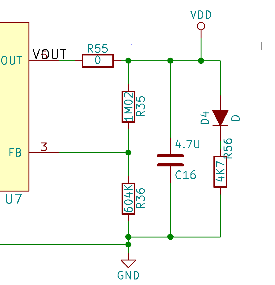
Yep, that simple of a circuit. Allow me to share a diagram:

The power of the blink
All this circuit does is light up. When the user inserts batteries and enables the circuit via a physical switch, the power flows through the regulator and lights up D4 which is a red LED. That’s it.
The crazy thing about this circuit? The LED indicator was not implement until rev 3 of the design! Prior to implementing this I only knew the status of the board when I put a DMM across the power terminals.
Throughout the testing of the above project and in many other projects, I have shorted things out by accident. When there is a power indicator LED on board that starts to blink because I’m dragging down the power rail, it’s easier to stop doing what I’m doing. If that isn’t there, sometimes the only indicator is another part of the circuit communicating intermittently or the switching converter starting to whine.
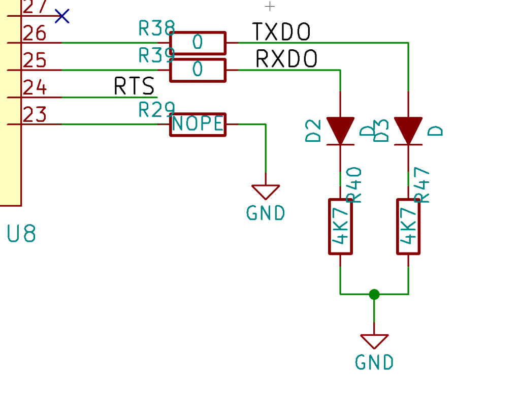
The serial blink
Arduino users will know this one well, there are LEDs that are attached to the serial lines. When you’re programming the board or transmitting back via the serial console, the indication is obvious.

You need to be careful with your serial lines, ensuring your LEDs don’t pull too hard on the lines. Set your current with the proper sized resistors so you don’t mess up the edges of your serial lines. When in doubt, take them out.
Blink is optional
You don’t need to end up populating these parts when you go to production. Your low power product might not be able to spare the milliamps of current. You can either “turn down” the resistor brightness by using a higher value resistor or you can leave the LED out entirely when you’re certain you have a stable product.
Your eyes are test equipment
While these circuits are super simple, it effectively re-purposes your eyes as test equipment. There is a high amount of light sensitivity in the human eye and even small changes like brightness difference or flicker will showcase that “something is different” if not “something is wrong”.
LED indicators will help you troubleshoot your next product. Be sure to add them to any/all of the following:
- Input power
- Output power – After your custom regulation
- Output power – After regulation happening on a chip or module
- USB power (if separate from your input power)
- Battery charging
- Serial lines
- Status LEDs