Categories
Analog Electronics

Fast Design

I’m finally starting to get it.

Apparently in the past the design work I’ve been doing is too slow. It’s too methodical, I have too much time to question my decisions. Well not anymore.

I’ve been working on a time sensitive project recently (sensitive enough that I feel bad writing this post at 9 pm on a  Saturday) and I’ve finally started to understand the reason the part vendors come to talk to me about power module this and fast design that. They come in with these nearly-done solutions and try pushing them on me, only to hear me say something like,  “Wow, I’d never use that”. I mean, where is the fun in using a power switcher that is damn near complete?

But now that I’m in a situation where I feel the need. I feel the question rising in me…”WHERE IS IT?!”  I expect the answer, the part I’ve been looking for to be sitting in large quantities, in stock at Digikey. I figure I have a very simple, very common problem that needs to be solved not just by me, but by many other engineers the world over.

Honestly, I was looking for a completely integrated module that converts from a 24V bus voltage down to a 5V bus voltage to then be branched with various linear regulators. But there’s nothing out there. No turnkey solution. No simple-as-hell solution. But I want it. I’m willing to pay for it.

And now finally I’m starting to see why they create modules with built in this or that. It’s because there are tons of people out there like me, just trying to move on and get the job done. I’m not quite ready to pay the $20+ price tag certain vendors want, but I’m considering it.

So kudos to all those chip makers out there who recognized the need. But until you have exactly what I want, I’ll be elbows deep in datasheets if you have a new part to show me.

Categories
Analog Electronics

The Rock Stars of Analog

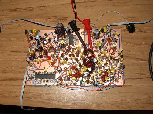
Over on The Amp Hour, I’ve been known to call ham radio operators, “The Rock Stars of Analog“. This is meant for the ones that are out there making their circuits using the dead bug method or otherwise. Jason Milldrum from NT7s.com has confirmed this belief with a picture in his latest posting about his RF kit making business:

Project X Prototype

I mean would you LOOK at that thing??? It’s awesome! Plus it transmits radio signals, so it’s just that much more magical. I know the theory behind RF, but I still geek out whenever I think about radio stuff. Anyway, thanks to Jason for posting the picture on his site and on Flickr. Check out his blog for more info as it comes available!

Categories
Analog Electronics

What Is A Power Budget?

Boy is it hot in here or is it just me? Why’s that gizmo over there giving off so much heat?

Power budgets are a necessity these days. Due to increasing regulation, we’re seeing devices that must comply with efficiency limits in their power conversion (using a switching power supply or otherwise).

So what is a power budget? Much like a budget you might have for your personal finances, a power budget shows where all the possible power will be used by a device to by breaking it down into components and categories. In some situations, you might be told up front that you will have 3W available to run your design. However, sometimes as designers we start by calculating the total power a system needs and then taking actions such as replacing parts or redesigning circuits to cut back power to an acceptable level. So why might someone want to do a power budget from day one?

  1. Power availability — While you might have more power today, it doesn’t mean you’ll have it tomorrow. Designing a system for 3 W power consumption may be acceptable now, but designing a lower power system may meet future regulations. And the trends in the industry point in that direction.
  2. Battery Life — If your device is running off a battery, you likely do not have a choice whether you are doing a power budget. You want to maximize the life of your device on a single charge (assuming it is using rechargeable batteries) and your customers want the same. Just a few weeks ago I was complaining publicly on The Amp Hour about my new device with poor battery performance. Doing a power budget will point to the components consuming the most power so you can later optimize for longer battery life (hopefully this was a design constraint from the beginning).
  3. Heat generation — Heat is an unfortunate side effect of working with electronics. However,  it also has a 3 direct effects on your product and how it is used.
    1. User discomfort — No one likes having a hot laptop sitting in their lap. Nor a cell phone that is uncomfortable to hold.
    2. Circuit robustness — An often quoted specification of an op amp is the voltage offset drift. This sensitivity to temperature can have dire effects in systems that rely on analog accuracy. However temperature changes can create conditions that are unfavorable and could even cause device failure (such as thermal runaway). The heat of the whole system can end up affecting individual components as the nominal temperature inside your device rises.
    3. Product lifetime — The lifetime of a product can be drastically reduced by higher than normal temperatures inside the device. Extreme temperatures can begin to dry out capacitors and cause others to fail catastrophically. While it is possible for systems to fail in a drastic manner, the more likely outcome is a product that does not last for its specified lifetime. An example might be a TV that has a less vibrant LCD after 5 years due to excessive heat and component drift and fatigue. If the product was designed to have lower heat, the product would have lasted longer. For more on how to design and prevent early failures, check out Dave’s video blog about heatsink design.
  4. Cost (sizing) — More power means you need larger components. Other than the obvious requirement of needing more space (duh), it often correlates to higher cost components. Not only will you need larger packages for your components such as op amps and comparators in order to better dissipate heat. You’ll also need a larger power supply with more reliability. If a 5W and 20W power supply with 12V output are compared, the 5W supply has smaller magnetics and less wiring because there is less total current that needs to pass through.

So let’s look at an example power budget (click for a larger version):

As you can see, not much more is required than your datasheets and a spreadsheet type program. Even simpler is a piece of paper but I prefer the built in math functions of the spreadsheet program. The first two columns (A&B) are simply identifiers to allow you to recognize which components correspond to which set of data. The next two columns (C&D) determine the multiplicative factor. If you have 5 components that contain 4 op amps per, then that will consume 20x the power of a device that has the same supply current needs but only one op amp per and there is only one on the board.  The next two columns (E&F) show how much current each individual component contributes and then the sum of all the components of that type contribute. Note that this parameter on a data sheet would be listed as “supply current” or “active current”. The “quiescient” number is when the device is in a resting state and will likely be much less than the active number (and not relevant for this example). Finally, the supply voltage is listed (in column G) to calculate power (using the formula P=I*V) which is listed in column I per device. All of these contributors are summed, an efficiency is estimated (I assumed a poor efficiency linear type supply) and the total power required input to the device is given. Further calculations could result from much of this initial data.

I would be remiss without mentioning something about power budgets: you’re still going to guess about certain things. In fact it will be many different things. You might not have perfect data about your components. You might not completely trust the “typical spec” of one of your components. This is the point where you design in a margin of error. However, just like many other aspects of engineering, this is where tradeoffs come into play. You might want to design in 4 times more power capability than you calculate (to feel safe), but there are cost and spec requirements to consider. You will have to determine how confident you are in your design and how many resources you have available to your design. In the above example where the 5V parts require 408mA from the supply (~2W), I might over spec the part by designing in a part that is capable of supplying 600mA. The (50%) margin of error allows for future expansion (might need to solder in an extra part or two) and also gives a cushion if anything was miscalculated. In some situations this 50% might be too much (think a very low-cost, high volume design) or might be too little (think a military, high reliability design). It all depends on the situation and requirements.

Power budgets can be very powerful depending on the amount of time and effort you put into them. Otherwise they are educated guesses which may or may not be helpful to your project; how helpful they are might also depend on where you are in the design cycle. As stated before, these budgets are more and more of a necessity in a world more power conscious and with devices that continue to shrink. Your customers will expect longer battery life and your products to have yet more features. Teach yourself how to do power budgets now and it will pay dividends for you in the future.

[xyz_lbx_default_code]

Categories
Analog Electronics Learning

Homeschooling

I have lots of thoughts about education, especially higher education. The theme that keeps popping up in my head though is that school isn’t too far removed from teaching yourself. Honestly, let’s look at the learning process:

  1. Encounter a “problem” that needs to be solved.
  2. Do background research and look at past examples of how it was solved.
  3. Apply your newly gained knowledge to the problem at hand.
  4. If a new problem arises that is not encompassed by the recently acquired wisdom, go back to step 2.
  5. Report on your findings to others.

Doesn’t this sound like work? Or studying on your own? Or doing a hobby project? How is this any different?

Since I’ve had this debate with friends before I can tell you what others say. They say that the classroom environment and being shown some of the methods before doing the problem is helpful. That having the theory explained directly helps the brain to acquire the necessary knowledge. That being able to step into the professor or teacher’s office and ask a question is a nice luxury to have. But does this always happen? I know I’ve had teachers I don’t understand (or very much disliked), notes that didn’t make any sense upon second reading and semesters where I’ve taught myself completely out of a textbook (and of course it happened to be the worst textbook of all my classes that semester).

Furthermore, there are resources today that allow individuals to continue learning on their own. Video resources like MIT Open Course Ware (OCW) can replace or augment self learning on particular topics. Message boards can provide a forum to interface with experts and to keep up on recent developments in your industry. The prices of equipment have nosedived in the past 10-15 years, allowing many more people to have a “lab section” in their house. And things like hackerspaces allow for social interactions and places to flesh out more advanced ideas.

So what’s really left? Motivation. When you’re paying $30,000 a year or are spending every Tuesday and Thursday in a classroom somewhere, you’re going to make the most of your time there. You’re going to do the homework and go get the help you need to figure out the subject matter because you aren’t allowed to put it off a month or a year. You’re going to be motivated by the piece of paper you receive at the end of your degree program saying that you completed all of the necessary requirements and did so while meeting or exceeding the expectations of your institution. Or you might even want to just prove you can do it. All of them really are valid reasons, they just don’t exist when you’re teaching yourself at home. External motivation is needed for many people (myself included) to pick up a book on a subject. In fact “motivation, momentary lapse of” is how this post came about. I was reading about active filters for a side project (where the motivation is showing off the side project and becoming “internet famous”) and I started thinking about how similar my current situation is to my former schooling. And all of the self-teaching and gained experiences are occurring without paying the $31,000 a year (yes, you read that right, tuition went up just since the last time I listed the number).

Do I hate higher education? No, I think there are some factors that make it invaluable to those that pursue it (and many more that benefit from the output). I may still try to get back to grad school myself some day. I love that there are institutions dedicated to research that might never get done otherwise. I’m glad that there are institutions that stress the rigor of the scientific method. I love that there are places where learning and advancing knowledge is the main purpose and task of those that attend. But all I’m saying is sometimes this happens in basements and bedrooms too.

Is learning at home without the structure of schools possible, especially in higher education? Does anyone ever teach themselves at home and why do you do it? What problems do you have with it? People currently enrolled in a University, do you find any fault with this thought?

Categories
Analog Electronics Learning

They Don’t Make ‘Em Like They Used To!

Being an analog engineer, I’m around “more experienced” engineers on a daily basis. However, a group of younger engineers often find ourselves acting much older than we are, shouting things like “Get off my lawn!” and “Back in my day…” (really, we had a whole list).

Anyway, another common one that comes up is “They don’t make ’em like they used to!”.  Do we as engineers know WHY they don’t make them that way anymore? Of course we do. The lower reliability and requirements for many more people to assemble the devices honestly doesn’t make sense these days. With lower priced labor the world over and low tolerance for waste and inefficient processes, I know I wouldn’t make the proverbial “them” that way anymore. It just doesn’t make sense.

But why am I mentioning this? In episode 12 of The Amp Hour, Dave Jones and I were discussing the Tektronix scope that I currently have disassembled and am attempting to piece back together in working order.  It’s the 485M, the military version of the very popular scope.  Right now I’m looking at getting the power supply back on its feet, the voltages were woefully low. More on that in later posts hopefully. For now, let’s concentrate on looking at the awesome design tactics and fabrications inside an old scope.

Note: I am a pretty bad photographer, please excuse any non-professional looking images.

A view of the quite complex button schema of old Tek scopes. Each button controls an individual switch, pot or selector switch. And yet it has many of the features of modern scopes match these exactly.

I LOVE modular design and this is a great example. If a technician (a Tek Tech?) found that a module wasn’t performing correctly this entire module could be switched out to check to see if it is indeed this module.

A closer view of the module. Of note is the resistor jumpered directly across the signal lines of the end connector. Perhaps this is a later fix for a customer issue. It’s also a good view of a mechanical connector that reaches all the way back from the front of the module. It’s a compound switch, pulling on it activates the arm in one direction and pushing on it does some other completely different action.

A close up view of the modular connector. I also like seeing the layout patterns done by hand before CAD programs were prevalent. Interesting to see where they flooded the ground planes.

A closer view of the analog components on one of the modules. Notice this was mainly resistors and a smattering of socketed op amps.

Another view of a mechanical arm reaching all the way to the back of the chassis. Likely a custom part as discussed on The Amp Hour.

This selector switch was the main voltage range switching. It had a compound action as well (inside was a fine tuning I believe) whereas the outside switch was the larger 1-2-5 multiple decade switching.

And finally, a view from the top. Note the >7 kV warning on the CRT tube. No touch!

So there it is, as Dave calls it, “nerd porn”. Isn’t it interesting to see how instruments were constructed not too long ago? It sure was more labor intensive and likely much more expensive than you can pick one up today on ebay. The benefit is that the hand-made and through-hole nature of this board makes it ripe for fixing AND without straining my fragile old eyes. Dangnabbit!

Categories
Part Review

Part Review: LT4180

A note about part reviews: I do not get paid to do reviews. I am either doing them out of the kindness of my heart, because they have some historical significance (as in the case of my review of the LM741) or most likely I think the technology is important and interesting. All opinions are my own and I would not suggest making any part choices based on the information in this article alone. Read some datasheets, they’re pretty informative.

No wire is perfect.

Basically, that’s the premise behind this chip, the LT4180. The real background is that when someone is providing power to a remote device they want the voltage to be accurate.

An example of this might be a USB supply to a device more than 20 feet away. The host (whatever is in charge of setting up communication and providing power, such as a computer) is supposed to supply 5V to the device (such as a printer or a mouse). In this case let’s assume that the device is very dependent on that voltage being correct, for one reason or another. The real problem is that the wire providing that power has some innate resistance to it.  Even a resistance of 1 ohm at 500 mA (the max current of USB) can cause a drop of .5V. That’s 10% of the intended voltage!

So what are the traditional options? Well, the best one is to have a separate set of wires known as “sense” wires. They detect the voltage directly at the device without drawing much current (likely by utilizing high input impedance op amps).  So the current that is powering the remote device will be sourced through one set of wires and the voltage at the device will be fed back to the whatever is supplying the voltage. In theory if the resistance of the wire changes (due to temperature, stress, etc), the controller will react and adjust the voltage up or down so the correct voltage is delivered to the device.

But what if you already ran your wires and you can’t run a second set to sense the remote voltage? You either design in a regulator on the device side (a good idea regardless) and source a higher voltage or you just design in devices that can handle a large swing of voltages. Neither is the best idea, though they are likely to be cheaper than using this part. At $3 minimum price you’re much more likely to find a cheapo linear regulator which you can put on the device end and then burn power there. You lose efficiency but gain a few points with the MBAs in your company.

Enter the LT4180. You can put this device in line with a voltage regulator, as shown on page 6 of this wonderful app note.

As a quick aside, you know LT cares about this product as Bob Dobkin, the co-founder and Chief Technology Officer at Linear, co-wrote the app note. Very cool, you don’t see high level execs getting their hands in on the action very often these days.  I was impressed at least.

Back to the app note itself, you’ll see that there is a switching regulator or linear regulator that is providing the initial voltage. Then this device sits between the voltage regulator and the wires that lead out to the device. Notice also that there are only two wires, a source wire and a return wire.

Now for the magic. It has two key pieces, explained in better detail in the app note, but summarized here.

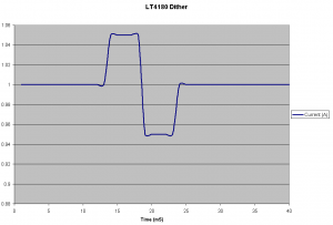
The Dither — LT calls it an algorithm, but in effect they are only stepping the supply current up and down by 5%. So if the initial regulated current is 1A, they step it up to 1.05 A and then down to .95 A (similar to what is shown below with a different timescale). Why? Because it’s effectively forcing an AC (varying waveform) through what was a DC (non-varying) channel.

Doing so allows you to gather the impedance of the channel without directly measuring the drop due to the resistance in the wires that are sourcing current. According to the app note:

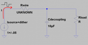
Because C is sized to produce an “AC short” at the square wave frequency, the interrogating voltage square wave produced at the power supply is equal to VSUPPLY(AC) = 0.1 × IDC × R, measured in Vpp. The voltage square wave measured at the power supply has a peak-to-peak amplitude equal to one tenth the DC wiring drop. This is not an estimate—it is a direct measurement of the voltage drop across the wiring over all load currents.

As illustrated below, the AC square wave is now shunted to ground instead of going to the load. This is how you can be certain it’s the actual resistance of the channel and not the channel AND the load. How cool is that?

The Control — Wait a second, how do they do that when they are not a part of the switching regulator or linear regulator? Nor does the regulator have any control lines with SPI or I2C or similar? LT illustrates 2 ways, but the basic idea is the LT4180 feeds back an analog voltage to the controller. This can then be used in myriad ways. The most straightforward way is to feed this voltage back to an error amplifier on the regulator, if it has one. The error amp will interpret any incoming signal as an error and correct the output. By dithering this signal by a little in either direction, the output current from the regulator can be made to vary. Other methods shown include feeding the signal into the trim circuitry (that controls the precise voltage allowed by certain regulators) or even feeding it into a discrete MOSFET based current source. With the voltage feedback signal there are certainly a lot of creative ways to feed this information back to your regulator/switcher to achieve the desired dither.

All in all, I was impressed by this part. I haven’t had it on my bench yet to try it out, but the idea alone made it intriguing enough to write about. Power is a really big market and growing and Linear Tech makes no secret of the fact that they are targeting the more obscure but lucrative problems such as this one.  I’d like to reiterate that the app note is fantastic for this part and the datasheet fills in technical details and specifications that aren’t in the app note. Hopefully I made what was already well written a little easier for others to comprehend on the first pass.

For people that have landed on this page from Google, I would prefer that you do not ask any design questions, I am not actively using this part and I’m sure there are many others out there that would serve you better. For everyone else, if you have any questions, please leave them in the comments. Thanks for reading!

Categories
Analog Electronics Engineering Learning

Follow Up Post: Electronics People Online

I really don’t have much to say in response to my last post about where all the electrical engineer sites are online other than: message boards. I alluded to the idea of message boards when I mentioned EEVBlog, though unknowningly at the time; I thought EEVblog was only videos. Working with Dave on The Amp Hour has shown me that a message board can really help hash out ideas (if you’re one of the content generators), get suggestions, or get questions answered (if you’re watching or reading and don’t understand something).  So I started hunting and found some other quite active electronics-only forums:

  • All About Circuits Forum — The main site is a great online open-source textbook that explains lots of electronics concepts.
  • Electro-Tech-Online — This is an intense amount of posts, namely about electronics.
  • Eng-Tips — This is actually a site for all types of engineering but the link is for the electronics part of the site.
  • EEVBlog Forum — Like I mentioned above, this is Dave’s forum and it has some great chatter going on it.

Then there are the hacker/maker/DIYer type forums. These often span multiple disciplines and include questions from people who may have never seen a resistor before but you can usually find some good answers (or answer some questions yourself if you are so inclined).

  • Instructables Community – Not limited to electronics but there are enough electronics projects that there are forums about it.
  • MAKE forums — Hard to find a bigger group of DIYers than MAKE and you know they’re bound to have questions for one another (or you!).
  • Hacked Gadget Forum — Alan’s site is usually a great aggregation of new, fun hacks that are popping up on the web; but the forums are a good place to ask about them!

Vendors often get in on the action as well. Why not? You buy the parts or kits there, you should be able to ask questions to others you KNOW are using the same things, right?

  • Adafruit Forum — Great way to ask about their popular kits. I’m disappointed they don’t sell the RF jammers that LadyAda designed though.
  • Sparkfun — The biggest hobbyist kit manufacturer out there, with over $12 million in revenue per year. With those kinds of numbers, you know people are hanging out at their site (even when they’re NOT giving away $100 of free stuff in a day). More people = more questions = more answers for you.
  • Parallax Forums — A kit maker that utilizes the BASIC Stamp chipset. When you can’t ask the Arduino heads about your issues, you’re going to need a forum to talk to.
  • Element 14 — They are a sub-company of Farnell, one of the largest distributors of components in the world. There’s extra useful content now that they own EAGLE (the CAD program)…but you can find some good general answers there as well.

There are also more specific types of forums out there, which makes a lot of sense. You wouldn’t care about working on precision op amps if you have a question about how to get an Arduino to control a relay.

  • DIY Drones — Want to know how to make a quadcopter? I bet this is a good place to ask about it.
  • AVR Freaks — Talking about AVR (the chipset in the Arduino) can get very specific. These members will help you with your specific questions.
  • Society of Robots — All things robotics, including the electronics needed for them.
  • DIY Audio Forums — High end audio electronics, built by you. Talk to others on the board to figure out if the sound is “warm” enough.

The thing is, even though I like the tailored nature of a message board (ask a question, get an answer), I’ve never really thought of them as a place for electronics people to congregate online. I was quite wrong though. The message board system is democratic in nature because those with the most involvement and the best answers will rise to the top as experts (though I like the StackOverflow/Chiphacker style for this better). Aside from the democratic nature, there can be contrasting voices in case there is a wrong equation or a better way to execute a design; this is important for checking engineering ego and ensuring a design will work properly. I think most of all though, it’s easy: easy for the website creator to set up and easy for people to understand how they work. All of these factors point to a pooling of collective electronic resources online.

So if you’ve never tried it out, give a message board a shot! You can find some great information, connect with some really smart people and maybe help one or two others as well. And if you find any not mentioned here, let us know in the comments.

Categories
Analog Electronics Interview

A Talk With A Science and Engineering Journalist

In this continuing series about the electronic food chain, I thought it would be interesting to hear the perspective of  someone who writes about leading edge technologies on a regular basis. We’ve already heard from an RF analog chip designer, an EDA software consultant and an electronics industry analyst. There will be more interviews to come in the future and suggestions are always welcome.

How do most engineers get information about projects they aren’t working on directly? I often hear it is from technical magazines. I have also been told by my mentors the benefit of keeping up to date on innovation that might eventually become the new standard. Just think, one day however many years ago, they were discussing WiFi in magazines–even though it was not widespread. And now it’s so standard that I’m using it for free in an airport while writing this post! The point is, keeping up on technology is important. But who gathers all this information for us to later digest?

Dr. Sunny Bains is a journalist and editor who covers many different scientific and engineering topics. You’ve probably seen some of her pieces in magazines like EEtimes, The Economist, Wired and many other large scale publications. I first found her site while looking around the internet for more writings on analog topics. She is very interested in both the use of analog information in electrical and biological systems and how these might advance computing power in the future.

Chris Gammell: What kicked off your desire to study these subjects?

Dr. Sunny Bains: Actually, the first thing I fell in love with was holography: I saw my first hologram when I was about 9 when I went to visit my dad in Canada and we took a trip to the Ontario Science Centre. They also had a laser show there, and between the two I got hooked on the technology. Science fiction also helped: I remember being inspired by various shows and movies: Star Trek, Blakes 7, Tron, 2001… Being a girl, I think I was a bit behind my male colleagues in doing actual practical stuff. A number of my male friends got their first computer when we were about 13 (ZX81). My younger brother had computers all through high school. I only got one when I had been at college for a year and decided to start a magazine about holography.

Holography took me towards lasers and optoelectronics, optical computing and signal processing, and then more widely to machine intelligence and vision.

CG: What made you decide to then pursue journalism?

SB: I always knew that writing would be part of my scientific future. I imagined myself sitting in my office doing work and writing articles when people asked me to. I don’t know why… I wasn’t a huge writer when I was in high school. But I actually started applying for science-journalism related jobs when I was still in high school.

CG: I see that you’re a lecturer and researcher at Imperial College in London . What kind of work do you target? Is it still holography?

SB: My favorite subject for some time has been neuromorphic engineering: building analog circuits with brainlike structures. However, I’m still interested in all sorts of things in the area of emerging computing technologies, machine intelligence, optoelectronics and displays.

My PhD (you can see the introductory stuff on my website) was about physical computation and embodied artificial intelligence. Basically, I’m interested in analog information, and using physics rather than digital algorithms to do processing. That theme often comes through in the writing I do these days on my blog.

CG: How about the work you do now?

SB: These days I focus on three things work wise…my company, my teaching (communication skills for engineers) and my writing. Although I will say, it’s hard to write in a recession: advertising budgets are slashed, the number of editorial pages go down, and freelancers like me are cut. Since my PhD I haven’t done any research in the science/engineering sense of actually doing my own work, just in the journalism sense of finding out what others are doing.

CG: Do you think this neuromorphic type work will lead to a singularity, a la Ray Kurzweil?

SB: I hated Ray Kurzweil’s book… you can see my review on my blog.

CG: If a student were to want to go into a field like neuromorphic engineering, should they focus on the analog side of things or the biological side of things?

SB: I think it’s MUCH more important for students to focus on analog electronics side of things. All that math is really hard, but once you’ve mastered it you can do anything. The biology you can pick up by osmosis I think. Anyway, you’re often focusing on some very small system in very great detail, and you’d have to learn all that at the time anyway. In some ways I wish I could be a neuromorphic engineer: I’ve got a fair bit of knowledge and a lot of interest. But I think being an engineer is the most important thing to make progress. That’s not to say that pure biologists don’t play a crucial role… it’s just that they can’t do much to create device: just find things/build models for the engineers to copy and, in some cases, do experiments to determine how well the engineers have done. Of course, I live in an Electrical and Electronic Engineering department, so I would say that…

CG: I’d be more interested in hearing more about your typical day, both as a publisher and a scientist. What is your typical day like?

SB: No such thing as an average day I’m afraid. From mid-September to mid-March I’m pretty busy with teaching and spend the most of the rest of my time running my company. If I’m lucky I write the odd piece if I have time. In the summer I try to work on other projects. That could be writing, research, or something for the company. This summer I’m working on a book about technical communication for engineers and physical scientists, and a new project for the company. As such, I don’t really have time to work as a scientist now; I only really did while I was doing my PhD (although that was for a long time). However, I think it’s quite likely that I’ll go back to scientific research at some stage as I tend to go back and forth between my various areas of interest.

CG: How do you first find out about the topics you write about? It seems like you often break stories that are very leading edge.

SB: I get my ideas from three main sources: conferences and other events (like one-off talks, workshops etc.), lab visits (where you just go to a lab and let them show off what they think is cool), and journals. I used to love going to the university libraries in the various cities where I lived and looking at all the new issues… Of course this is all done electronically now (no photocopying, hooray!). I’ve got some great stories by just seeing patterns in papers over a period of time. I do wish I could go back to writing regularly again. I know I could write more on my blog, but it was always supposed to be a byproduct of my freelance work, not a substitute for it.

CG: Do you have any predictions on the future of analog (since your articles are often very forward looking)?

SB: I am convinced that analog is the way to go for applications that are heavy in signal processing, and especially AI. Unlike with symbolic information, the “meaning” of signals does not always translate well into bits. Probably the story in the past that I’ve covered that exemplifies this best concerns Leon Chua’s cellular neural network. But the whole of neuromorphic engineering is built on the same idea: don’t break things into bits if you can just as easily use physics to do the computation for you.

Many thanks to Dr. Sunny Bains for taking the time to talk about her line of work. I was actually surprised when I first learned that she had so much exposure to neuromorphic engineering, a topic someone had previously suggested on the skribit portion of this site. It’s interesting how those futuristic ideas seem to dovetail with much of the analog knowledge of today; that often the most effective signal processing is still done in analog. Hopefully we’ll continue to see this trend and I’ll be able to write about it here.

If you have questions for Dr. Bains, please leave them in the comments!
Categories
Analog Electronics Podcast

Podcast #1: Introduction and Circuit Analysis

This is my first podcast ever!

Sure, it’s something different, but give it a listen and let me know what you think in the comments!

[display_podcast]

Categories
Part Review

Part Review: LM741

We all have to start somewhere.

I’ve been thinking about my posts as of late. Moreso, how I can offer something of substance to readers. At least substance that is usable on a daily basis. What do EEs want to read when they get to this site?

I came up with part reviews. I started something similar at my other project, Electricio.us. Spec sheet analysis is a critical skill for any analog engineer. It’s also is time consuming and hard to keep up with. So why not have a few choice parts highlighted on here? I don’t plan on reviewing the newest and hottest parts…but maybe the most useful. So let’s start with the LM741.

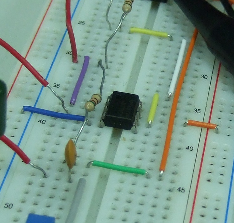
a uA741 op amp in action on a breadboard

A 741? These are parts I joke about, not parts I use on an everyday basis. But like I said, we all have to start somewhere. I’m sure many of us started using this part in electronics labs and at home in hobby projects. It’s the quintessential beginner op amp and it was one of the first ever designed.

LM741 datasheet from National Semiconductor

Pros:

  • Cheap — Being made by multiple vendors (necessarily called the LM741 but probably containing the number 741 somewhere in the title) really can help with cost.
  • Standard pinout — Sometimes even more valuable than having something cheap in the first place, being able to find a drop-in replacement can be a godsend when in a bind. This has been doubly true with the economic downturn. Sure, the part being out for 42 years doesn’t hurt either. People managed to figure out it’s pretty popular since it first arrived on the scene and duplicated this trailblazing part’s pin assignments.
  • Nulling circuit — As we’ll see in the “cons” about this part, the offset voltage is horrible, but the tuneability of the part is a nice feature if you have to use this part. The “offset null” pins give you access to the 1K emitter resistor circuit, basically allowing you to drive the input voltage on one side of the op amp higher by giving a different resistance for the bias current on the input stage. This effectively raises the voltage on one side of the input or the other (inverting or non-inverting). Pretty neat stuff!
  • Bandwidth — For an old part, the bandwidth on the 741 is 1.5 MHz. This is set by the internal capacitor, which acts as a pole inside the circuit and limits how fast the circuit can respond. This is extra interesting because the 741 was the first part to ever do this inside of the IC itself; previously you had to set the compensation capacitor externally. At 1.5 MHz, this old geezer of a part can still get up and move like a jackrabbit.

Cons:

  • Offset voltage — As you can see above, the nulling circuit is necessary because the offset voltages can get pretty extreme on the inputs of this op amp. “So what?” you say. Well, this causes issues when any kind of precision is required. If you put in a 1 volt signal into an LM741 that is set up in a buffer configuration, the 5 or so mV of offset voltage between the inputs will get passed directly to the output! That’s .5% of your signal right off the bat! And if there is any gain in the circuit (i.e. it being set up in an inverting or non-inverting configuration), then your offset gets multiplied by whichever gain you apply to the circuit! That means for a gain of 10, your 1V input signal now has an output offset of 50 mV! Say goodbye to DC accuracy!
  • Offset voltage drift –Even if you decide to “dial in” an offset null resistance on the proper pins, this is only accurate at the temperature you were at while correcting the offset. For every degree change, there is another 15 uV of voltage offset.
  • Bias current — We all know that in an ideal model of an op amp, you assume there is no current flowing into the inputs terminals. Well, that’s never really the case, and having any current flowing into the terminals can cause DC offsets once that current flows through resistors (such as in a non-inverting amplifier configuration). The standard bias current spec’d on this part is .1 to 1 uA. That’s nothing to write home about, especially if you care about DC accuracy. The downer on this poor spec is that there isn’t an internal “knob” to help with the bias current; you just have to deal with it and try to design around it.
  • PSRR — Though it’s not the worst I’ve ever seen, the PSRR on this part isn’t great either. At a typical value of 77 dB (use 80 for easy math) that means that any noise appearing on the power rails will show up 10^-(80/4) times on the output. So if you see a 1V transient on a 15V supply rail (gah! huge!), then you will have a 10 mV spike on the output. This can cause some serious noise problems down the line and most op amps I’ve been looking at these days have been well north of 100 dB PSRR.

This part is old, no way to overlook that. But it is still relevant part and is the basis for many parts that exist today. That’s pretty impressive some 40 years later. The downsides show the part’s age but are a symptom of the technology and the time this part was developed. The transistors are BJT, compared to the MOSFET based parts of today; many of the specs are guaranteed to be worse on this fact alone (though not the speed nor the power handling ability).

If you have a simple need for an op amp and you know how to properly account for all the shortcomings in this op amp, it’s a fine choice. Like I said above, it’s low cost, easy to use and plentiful in supply. And if history has shown anything, it’s that this part is not going away anytime soon.

So this was my first part review. I think in the future instead of running down the list of a lot of the specs like I did here, I would focus instead on one or two of the spectacular properties of a chip or the extremely underwhelming properties of a chip. Comparing all the middle of the road specs is a waste of everyone’s time. I wanted to make sure I covered a few things here as a baseline for future reviews though. I’d also like to step outside the bread and butter parts of an analog electrical engineer’s part drawer (the op amp) and review other types of components.

If you have any you would like to see reviewed in the future or have any thoughts about this review, be sure to leave a note in the comments.

Thanks to 畢業了吧 for the photo