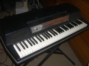
Things get old. Things eventually do not work anymore. Even the best engineers cannot design a system for part failures (unless they have triple redundant systems, like NASA). It is for this reason, I have decided to document on my blog the tune up of my Wurlitzer 200A electric piano (seen below) as opposed to the usual analog issues in the workplace today.
I mentioned this piano in my post about keeping it simple, namely not replacing EVERY component, only the ones that require an upgrade/replacement. It is a famous piano that can be heard in many types of music, spanning rock, soul, jazz and more. Similar to the Fender Rhodes, the Wurly can be characterized by a darker, more over-driven sound and a built in vibrato (constructed from a simple oscillating circuit).
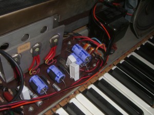
There are two components on these boards that need to be replaced the most often. The first is transistors, due to thermal stresses when they are over worked. In the case of my Wurly, the power transistors (seen below bolted to the large metal heat sink on the left) have started corroding, but have also had reduced output due to thermal stresses over the years. The board has upwards of 250 V and these transistors are ready to be replaced.
The other element that commonly needs to be replaced are the capacitors (the purple barrels seen above), specifically the electrolytic capacitors. An electrolytic capacitor is constructed by soaking paper in an electrolyte and sandwiching it between two aluminum plates (then attached to the leads of the capacitor). After about 10 years or so, the electrolyte begins to dry out and the capacitor degrades. Sometimes this can lead to a catastrophic breakdown (think “POP” or “BOOM”) or it can just mean that no signals will get through. Whereas I think of capacitors being frequency-dependent resistors (where the lower the frequency, the higher the resistance), these capacitors instead have resistance at ALL frequencies, due to the fact that the dielectric constant has gone from that of electrolyte to that of air. The final effect of all of this is a poorer sound, especially at the higher frequencies that are supposed to “pass through” a capacitor.
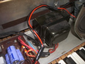
I am also hoping this will take care of some of the “hum” sound (most likely from 60 Hz); I’m hoping this will be resolved once the power filtering capacitors are replaced. I think that the ripple current may be higher since the capacitors have slowly degraded. This will impose the 60 Hz from the wall power onto the signal coming from the vibrating reeds (through the capacitive pickup). I also am wondering if the transformer (below) requires replacement, but I think I will replace the capacitors and transistors first.
That’s all for now, I will update more as I actually replace these capacitors. For now, enjoy the pictures and the sound samples (above links to Last.fm).


9 replies on “Replacing capacitors on my Wurlitzer 200A electric piano”
awesome blog dude!!!
where did you find that wurly?
[…] concepts with the final product in mind. There was much less focus on using existing products (i.e. discrete transistors) to create something new or to solve a problem. I do not think that it is a huge problem, as some […]
[…] though I got the capacitors and transistors in for my Wurlitzer 200A, I decided to write about something else before I started documenting the hopefully successful […]
[…] it seems that I may have broken the amplifier on my Wurlitzer 200A. This after I took my sweet ol’ time getting all the replacement parts in from Mouser. After […]
[…] Capacitors — At DC, a capacitor is essentially an open circuit (think a broken wire). If you apply charge long enough (depending on the capacitance), it can consume some of that charge; after it is charged it will once again act like an open circuit. When considering AC (varying) signals, the best way to think about a capacitor is like a variable resistor. The thing controlling how much the capacitor will resist the circuit is the frequency of the signal trying to get through the capacitor. As the frequency of the signal goes up, the resistance (here it is called “impedance”) will go down. So in the extreme case, if the frequency is super high, the capacitor will appear as though it is not there to the signal (and it will “pass right through”). Taking the opposite approach helps explain the DC case. If the signal is varying so slowly that it appears to be constant (DC), then the impedance of the capacitor will be very high (so high it appears to be a broken wire to the signal). […]
[…] is that their program is well suited to handle rapidly changing inputs. I plan to re-construct my Wurlitzer 200A schematic in LTSpice in order to better understand some of the parameters affecting the sound and maybe even […]
[…] being able to get it working since. When I messed up last time I was actually trying to replace the capacitors and transistors that had dried up and what I had thought was causing considerable hum in the circuit. However, […]
[…] and change the world. And every resistor value of a circuit board they encounter. And mess with the capacitors. And change the model of the op amps. Oh, and don’t forget to swap out transistors. […]
this does not look like a A200, but the old only 200.. the plate is different