Categories
Analog Electronics Music

Wurlitzer 200: Fixed

I am very excited to announce that the Wurlitzer 200 is fixed and operational. I say Wurlitzer 200 instead of 200A because a nice chap emailed me and let me know that I actually had an earlier model. Either way, it works and it sounds delicious.

Wurlitzer 200

Really this post is to gloat a little and to post the sound samples I recorded with my friend Joe. He is a great piano player and shows off the awesomeness of the Wurly better than I ever could. I also wanted to lay out some future posts about the Wurlitzer that I plan to write:

  1. Things learned about fixing the Wurlitzer. Schematics and my own drawings included.
  2. The importance of grounding for a clean signal and how it can affect other types of electronics.
  3. How transistors work and how the broken transistor on my Wurly was causing me grief.
  4. How fuses work and when to use them.
  5. Any others requested/suggested through the skribit box on the right.

Finally, here are the sound samples Joe and I put together today. It was fun recording again. For full disclosure, there was digital delay on the Wurly and there was some processing on the drums too. Also, I apologize that the drum tracks are a little loud; it’s because I’m an electrical engineer, not a sound engineer (and definitely not a professional musician). Enjoy!

Categories
Analog Electronics Learning Music

Update: Wurlitzer 200A–Still in pieces

I thought I would update on my hobby subject for tonight since I mostly worked on my Wurlitzer 200A electric piano instead of writing the post I meant to. I’m just now getting back into working on my electric piano after previously having zapped something on the board and not being able to get it working since. When I messed up last time I was actually trying to replace the capacitors and transistors that had dried up; I had thought these were causing considerable hum in the circuit. However, since deconstructing the piano I found a modification to the wiring scheme between the two speakers and the output headphone jack located at the bottom of the board. I found that on the headphone jack someone had wired in a simple RC circuit, presumably for filtering the headphone output. However, the small wiring scheme they used and meant to ground to the chassis had been disconnected, possibly by me. This floating output circuit could have been the problem all along! Only time will tell but I will feel silly if that was indeed the culprit.

Still, I always prefer a silly mistake that is found and easily corrected (with damage only to my ego) , as opposed to a difficult error that cannot be fixed or worse, found. See the pictures below of the destruction that has befallen my piano and hope that I can get humpty-dumpty back together again.

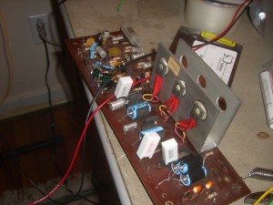
The main board, removed from the chassis. With new electrolytic caps.

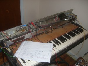
The piano with the chassis and the board removed. The speaker assembly and the transformer are all bolted to the main chassis, which is convenient when you want to work on the action of the keys (how the hammer hits the tone bars).

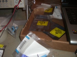
The slew of new components I got in from my online order…and now may not need?

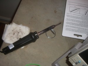
It’s not the wand, it’s the magician. In this case, the wand is a piece of junk soldering iron from Radio Shack. Maybe Santa will bring me an industrial voltage controlled soldering iron.

Categories
Analog Electronics Learning Music

Replacing capacitors on my Wurlitzer 200A electric piano

Things get old. Things eventually do not work anymore. Even the best engineers cannot design a system for part failures (unless they have triple redundant systems, like NASA). It is for this reason, I have decided to document on my blog the tune up of my Wurlitzer 200A electric piano (seen below) as opposed to the usual analog issues in the workplace today.
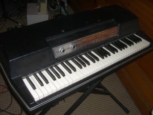
I mentioned this piano in my post about keeping it simple, namely not replacing EVERY component, only the ones that require an upgrade/replacement. It is a famous piano that can be heard in many types of music, spanning rock, soul, jazz and more.  Similar to the Fender Rhodes, the Wurly can be characterized by a darker, more over-driven sound and a built in vibrato (constructed from a simple oscillating circuit).
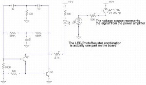
There are two components on these boards that need to be replaced the most often. The first is transistors, due to thermal stresses when they are over worked. In the case of my Wurly, the power transistors (seen below bolted to the large metal heat sink on the left) have started corroding, but have also had reduced output due to thermal stresses over the years. The board has upwards of 250 V and these transistors are ready to be replaced.
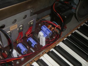
The other element that commonly needs to be replaced are the capacitors (the purple barrels seen above), specifically the electrolytic capacitors. An electrolytic capacitor is constructed by soaking paper in an electrolyte and sandwiching it between two aluminum plates (then attached to the leads of the capacitor). After about 10 years or so, the electrolyte begins to dry out and the capacitor degrades. Sometimes this can lead to a catastrophic breakdown (think “POP” or “BOOM”) or it can just mean that no signals will get through. Whereas I think of capacitors being frequency-dependent resistors (where the lower the frequency, the higher the resistance), these capacitors instead have resistance at ALL frequencies, due to the fact that the dielectric constant has gone from that of electrolyte to that of air. The final effect of all of this is a poorer sound, especially at the higher frequencies that are supposed to “pass through” a capacitor.

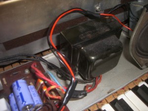
I am also hoping this will take care of some of the “hum” sound (most likely from 60 Hz); I’m hoping this will be resolved once the power filtering capacitors are replaced. I think that the ripple current may be higher since the capacitors have slowly degraded. This will impose the 60 Hz from the wall power onto the signal coming from the vibrating reeds (through the capacitive pickup). I also am wondering if the transformer (below) requires replacement, but I think I will replace the capacitors and transistors first.
That’s all for now, I will update more as I actually replace these capacitors. For now, enjoy the pictures and the sound samples (above links to Last.fm).