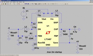
One of the biggest conflicts of interest in the life of an analog engineer is that the best tool available to them is on a computer. SPICE is a program that was originally developed at Berkley to model silicon level physics to help prototyping (similar to “bread-boarding”) before the final product was produced. While it still remains a valuable tool for chip designers, it has also been broadened in scope and size to include larger designs and higher level models since it was first created. The idea is the same, that electrons basically move in the same way and that potentials in a circuit (voltages) can induce a certain behavior. So as long as the models for high level components (say an op amp or a buck converter) are well thought out, they often can represent the real world equivalent quite well.
I have some experience with SPICE and it is very helpful for both creation of new circuits and analyzing existing circuits for weaknesses. And since I have started using it, I have tried many different versions and deviations on the original SPICE program, but I have found I like LTSpice the best. Best of all, it’s free. Like, really free. Even if you don’t know anything about circuits (analog or otherwise) and only plan to use the program once, it doesn’t matter!
LTSPICE IV — Free download! (not sponsored, I just really like the free-ness of the program)
I’m going to try my best to resist making this post sound like a puff piece, but I’ve only recently discovered LTSpice and I really enjoy how it works (even compared to similar programs that have licensing feels). The interface is the exact same as LTSpice III, so if you know that program, you won’t have much trouble with switching over to the new version.
Let’s go over some of my previous complaints about the program and how they have been been put to rest:
- No central area to enter model information — One of the things I had enjoyed most about the SPICE programs I had used previously was that there was a central location to put all of your model files for any models of components you might have had. Then when you were ready to use DXYZ123 in your schematic, you just match the component type (Diode, Transistor, etc) and then name it the same as your text file. In LTSpice, you have to enter the model information on the front page as a SPICE directive. While this is similar to putting the models in a separate file, if you plan on using a lot of non-LT parts in your design, your schematic can get quite cluttered.
- Harder to create high level schematics — OK, this was really me. I was used to different hot keys in order to modify the schematic. Really this was my impatience at learning a new system, but once I did, it’s not too bad entering new information.
- Only Linear Tech component models — While this is a bit annoying, it is also quite understandable since they are giving you a complex SPICE modeling program for free. There are some common passive components throughout, and you can add to libraries to add even more passives, but once you get into active parts, they are exclusively LT. See point number 1 above in order to add models for Analog Devices, National Instruments, Maxim, etc parts.
OK, enough of the downsides, let’s go over what I think sets LTSpice apart from its more expensive competition:
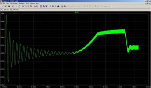
- Power consumption calculation — Hold down the alt key and on any component in your schematic and you can map the power consumption on the simulation graph (see below). This equation can be quite complicated, especially for the models that are included for all of the LT parts. As power saving techniques become more and more important to electronics manufacturers, this feature becomes indispensable. If you’re not too big on efficiency but happen to care about temperature, this same feature can estimate how much energy (still in Watts) the individual components will emit based on the power dissipated. At the very least, even if the simulation is not exact in how much power is burned during processing of a circuit, you can graph the rates of all power consumption and see which is the biggest consumer and try to optimize that part.
- Efficiency calculation — Again, this will become more and more important to engineers as the focus on simple fixes in products for energy efficiency becomes more prevalent. Here you have to name the input and output signals specific nodal names, but once you do, the program will automatically calculate how much energy is being converted into useable energy and how much is being wasted. An example would be in a circuit made to regulate 10V down to 5V. This can be done with efficiencies up to 90%, but some amount of energy will be dissipated by resistors or active components like op-amps. Ya gotta spend energy to make energy.
- Dual Core integration — This is one of the biggest improvements from LTSpice III (really it was called SwitcherCAD III) to LTSpice IV. Now they have support for dual core processors which are quickly becoming the standard in computers from desktop to laptop to netbooks (OK, not yet on netbooks). Either way, if you are only using one available core for your simulations, you’re running at roughly half of what they COULD be running at. I have a dual core on my current machine and LTSpice quickly used up the available resources and the quickness of results showed the difference. LT is still working on the bugs on some types of computers processors, so they only run on one core, but hopefully it will be functional on all types of machines soon.
- Graphing function — This isn’t any different from LTSpice III, I just thought I should mention how much I like the graphing abilities of this program as compared to others I’ve used. LTSpice really grabs hold of the graphic model in SPICE and runs with it; their software allows you to click on a node to find out the voltage (even after the simulation is completed) or to click on a particular component to find out how much current has gone through that part throughout the simulation. The point and click method allows for quick diagnosis of problem components and circuit layouts.
- Dynamic Simulation — Linear Tech is a big player in the switcher market (a switcher basically takes input power and pulses an output–usually through a capacitor or inductor–to produce a stable output). However, the side result is that their program is well suited to handle rapidly changing inputs. I plan to re-construct my Wurlitzer 200A schematic in LTSpice in order to better understand some of the parameters affecting the sound and maybe even inputting and outputting sound files (you can do that with raw formats). More on that in later posts.
All and all, I know I sound like I’m gushing, but I always enjoy free software that is made well. It’s like some of the open source programs I love, but with a company behind the product supporting it (and yes, trying to sell you chips). There are many other great SPICE programs out there and some of very worth the fees they charge. However, if you are looking for a quality program at no cost, I would suggest LTSpice.
Do you know of other SPICE programs? Do you like them better for one reason or another? Please let me know in the comments section.
[xyz_lbx_default_code]


19 replies on “Best Free SPICE Program”
mmmmmmmmmmm, free software. I also like Octave, the free MATLAB-like software. Especially since you can look online and usually find an m-file laying around that does what you want and reuse it without any changes.
i prefer ALLspice….no, no…i vaguely remember using SPICE in college. That’s all I got.
I kinda like Old Spice…
[…] Thermal budgets become important in any new PCB design and you should be mindful of them. Some SPICE programs even allow you to check out what the heat/power dissipation will be before putting the components on […]
[…] regulator to understand what is inside of it. To illustrate, I will be using my version of LTSpice, which is free (awesome!). Also to note, there are lots of great programs out there to help you design this stuff […]
SPICE is free and open source. All other flavours of SPICE, free or not, wraps an interface around the free simulation engine. Ah…I remember the days when I used to type in the netlist by hand in a text file and get text files as graphical outputs…you kids nowadays with your fancy plotting tools. 😉
I was also recently checking this free evaluation tool by Spectrum-soft.com (Micro-Cap 9) as well and really seems good to me, specially because it does SPICE simulations on analog but includes digital analysis in the same tool. I find the sliders to test different component values really cool. Do you know it? How would you compare it to LT’s one?
Hi Genis,
I’ve used MicroCap9 and liked it too. I believe their component modeling is pretty advanced compared to most SPICE tools. However, I didn’t feel it had the ease of GUI that LTSpice had. I could just be biased for some unknown reason though. Thanks for letting everyone know about it!
~Chris
I’ve used various incarnations of Microcap for about 15 years. I find the ease of producing good looking schematics is way better than LT Spice which seems downright awkward to me. With MC you can use S-parameters or Spice models. Most manufacturers make their S-Params or Spice models available as simple text files.
[…] simulation can perfectly match what will happen in the real world. If you are an analog designer, simulate in SPICE to get the large problems out of the way and to figure out how different inputs will affect your […]
[…] it down into smaller pieces and try and figure out the transfer function or take the plunge and try it out in SPICE. This will help you to better understand how the circuit might behave when presented with certain […]
hey does anyone know how to calcultate power of digital circuits using LT spice.
By digital circuits i mean registers,multiplexers and others
[…] Basic laws — It is amazing to me how much depth is needed in electrical engineering as opposed to breadth. You don’t need to know all of the equations in the back of your textbook. You need to know 5-10; but you need to know them so well that you could recite them and derive other things from them in your sleep. A good example would be Kirchoff’s laws. Sure, they are two (relatively) simple laws about the currents in a node and the voltage around a loop, but done millions of times and you have a fun little program called SPICE. […]
[…] say that Google SketchUp is one of my recent favorite prototyping tools. While it’s not the SPICE simulation or the rapid circuit prototyping that most people might think of for analog system designers, it is […]
Thanks for the reminder on the ALT key to calculate the power plot! It is also helpful to know that once you get the power plot as you show in your article that holding the CTRL key while clicking on the name of the power dataset in the graph window (usually named with a long equation), you can get average power consumption over the time interval that you are currently zoomed to! Great!
OK, so I just tried it. After struggling getting what I thought was a fairly simple circuit to work I decided to strip it down to something trivial. I start with a simple NPN switch and that works fine. I substitute an NMOS transistor for the NPN and I simply cannot get it to work the way it should. Simple DC analysis of VCC feeding a load resistor feeding an NMOS switch with a separate power supply for the gate. Am I missing something here? Is the NMOS transistor model flawed in LT Spice?
You may also like TI's simulator – http://focus.ti.com/docs/toolsw/folders/print/tin…
LTSpice will easily accept other spice models as Subcircuits . You need to do your home work before public commenting
@Alan Bate Electronics Perhaps you should learn to read dates and do your own homework before you go around accusing other people of not doing their homework. This article is 8 years old. All of the documentation for LTSpice that talks about adding third-party models is roughly 6 years old.