As promised, this post is a follow up post to explain the real-world behavior of an op amp. Here we will continue to anthropomorphize op amps in order to better understand their behavior and what they “want” to do. Also, we will look at some more complicated (but common) op amp configurations so that they are easily recognizable. Let’s begin.
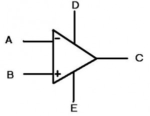
First, let’s look at the symbol for the op amp:
Whoa-ho! What the heck are those? Last time, there was only 3 lines coming out of the triangle and now there’s five! They’re multiplying!
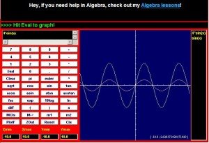
Really the “D” and “E” inputs are the power inputs to the op amp. This means we are no longer simply dealing with the “ideal” case and are now going to look at the behavior with some realistic expectations. I know that when I was first learning about op amps, I was perplexed by this idea. I thought, “Well what is the point of putting power into an op amp? What do I get for it?” The idea is that as long as the signal at the input (or more accurately the difference between “A” and “B” is smaller than the power at the “D” and “E” terminals, then the op amp can amplify the signal. This gets very useful once you start encountering signals that change over time, or AC signals (as opposed to DC signals). Let’s look at this idea below:
Special thanks to CoolMath.com for the graphing program!
On the top left, we see a SINE wave, which is one of the simplest time varying signals there is. Amplifying this signal would not shift the signal, but instead would make the entire range of the signal larger. If we used a 4x amplification, then we would get the top right picture with the larger signal. Notice in the bottom picture the overlay of these two signals. They do not SHIFT up, but instead look like they are stretched. The easiest way to think of all this is at the extremes. If in the first picture the highest point was 1 and we had 4x amplification, then the output would be 4. However, the middle point is 0 and that multiplied by 4 is still zero. Hence the reason the overlay shows the extreme highs and lows being “stretched” the most. Also, it is important to note that these are analog signals, so EVERY point in between the extremes is being amplified.
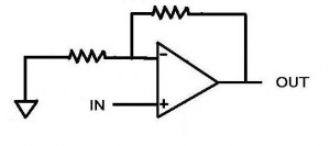
The power coming into the op amp also restricts how much the op amp can amplify a signal. Not only that, but sometimes you don’t even get to go to the limits! Say you have +15 volts attached to “D” and -15 volts attached to “E” (most op amps have lower voltages these days but +/- 15 volts still happens sometimes). Now let’s say you have a 1V signal coming into a non-inverting amplifier (shown below). The gain on this amplifier is set to 15 by making the top resistor 14 times less than the resistor connected to the ground (non-inverting amplifiers have a gain of 1+R(top)/R(gnd)). So our 1 volt signal is placed at the non-inverting input (the plus) and the op amp says “15 volts, coming right up!”. Ah, but the op amp doesn’t quite have it. The op amp outputs 13.4 volts are so and then stops. “But WAIT!” you say, “why can’t this op amp output as much as I wanted? The ideal ones can output INFINITY. Can’t I just get one of those?” The short answer: no, you can’t. Op amps have internal protection circuitry that limits how high the input to the op amp can be in order to protect it from blowing up. Additionally, the op amp must consume some of that power in order to actually amplify the input signal; this will be expounded upon in further posts (the internals of an opamp).
The final point in this continuing discussion about op amps, is known as slew rate. Really it is a discussion of how fast an op amp can go and is limited by capacitance. Inside of any op amp, there is a capacitor, or rather a bunch of components that act together as one capacitor. This creates a required charge time for the internals of the circuit (for a more advanced look at this topic, check out the allaboutcircuits.com article on capacitors and calculus). The end result is that the op amp has some limit to how fast it can “decide” what the output should be. If we think back to the signals above that alter with time, we can imagine a situation where they would vary so quickly that an op amp would not be able to keep up. The end result is that a circuit such as the non-inverting amplifier shown above has some frequency above which it can no longer accurately amplify. This is known as the bandwidth of the circuit and has implications in many audio, measurement and communication industries.
This post discussed some of the real world aspects of op amps. The next post will discuss the internals of the op amp, such as the transistor setups. Imperfections in the silicon and the realities of material science will show us that more of the “ideal” op amp model is not possible in every day life; some potential topics are the input bias currents, the voltage offsets across the input terminals and how they can affect everyday circuits.
[xyz_lbx_default_code]


