A background
Switching regulator, buck converter, boost converter, SEPIC, flyback, push-pull, buck-boost… do you know what the heck these things are??? Because I sure didn’t when I was getting back into analog electronics. Now thanks to new interest in power efficient electronics, they are starting to come front and center on the electronics stage. Hopefully this article will give you a better understanding of what they are, what they do, where to use them and issues with noise.
OK, so before we get to the real topic of this post, what do switching regulators do?
Switching regulators allow you to translate one voltage into another. They allow you to take a higher voltage and translate it to a lower voltage or a lower voltage and go to a higher voltage.
“Eureka!” you cry, “Chris has found the solution to all of our energy needs! We just hook a bunch of these switching doo-dads up and we’ll have unlimited power!”
But no, it’s not that easy. Switching regulators go off the fact that you can take a voltage and translate it to a different voltage, however, the power stays the same (in an ideal case). Meaning if you have 5V coming into a circuit and you have a portion of that circuit that needs to operate off of a 15V supply, you can use a boost converter or something similar and crank up the voltage. Say you have 150 mA (at 5V) coming in, when you convert it up to 15 V, you’ll have 50 mA available to whatever needs the 15V power. Notice in this (ideal) case, the power stays the same (750 mW).
It is a similar story when going down in voltage. However, there are many more options when moving down in voltage: switching regulator, linear regulator or even a passive element (like a resistor or a diode). You use a switching regulator because they regulate the output voltage (unlike the voltage drop across a resistor or a diode) and they don’t waste power like a linear regulator. If you want to go from a 20 V input down to a 5V output, a linear regulator would just “burn” up that 15V in the middle. With a switching regulator, most of the power is conserved (assuming you are running in the optimized voltage ranges…and there are a ton of different models to choose from so you can find the right range).
Finally, real quick, where are these used? Well, the hot new talk of the town has been renewable energy. “I can get 95% efficiency?” you ask, “Why wouldn’t I pay $4 per chip to do that?”. And really, the power efficiency isn’t just the garbage everyone seems to be spewing these days about saving energy for savings sake…it actually can help you make a better product. If you are in a heat sensitive situation, you don’t want to use a linear regulator to get your required voltage. In the above example if you are going from 100 mA at 20V and the output of the linear regulator is 100mA at 5V…that means you are burning 1.5W just regulating your voltages. With a switching regulator you can save a good percentage of that (for battery or “green” devices) and you can reduce the heat in a sensitive application. Plus, if you’re trying to go from a lower voltage to a higher voltage, you’re out of luck with linear regulators.
Switching Noise
Nothing in life is perfect. Switching regulators aren’t 100% efficient, there are limits to how much you can convert voltages (1000v down to 10V usually isn’t possible…or smart) and even in the best cases a switching regulator will introduce noise into a circuit. For the ways I have mostly used switching regulators (supplies for digital circuits), switching noise isn’t that big of a deal. If you are supplying 5V to a piece of flash memory, the part will probably not care if there is 100 mV of noise “on top” of the 5V signal (meaning the actual power supplied would bounce between 4.9V and 5.1V). Same for supplying power to LEDs or other non-analog situations. However, if there are any measurement components in your design or any even slightly sensitive analog portions, you should consider how the switching noise will affect your output.
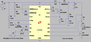
So why does switching noise occur? To answer that we really need to look at a switching regulator to understand what is inside of it. To illustrate, I will be using my version of LTSpice, which is free (awesome!). Also to note, there are lots of great programs out there to help you design this stuff (Webench, for example). Just don’t want to leave any of the vendors out, especially when they give out sampled parts. For this example, we’ll look at the LT3755, which EDN (and me by extension) showcased in an article about creating simple LED lighting for your home. The application here would be to boost an input of 10V to an output of 40V to light an array of up to 14 1A LEDs.
Notice the LEDs (D2 in the diagram) are where the final current and voltage is being delivered. The waveform for the inputs and outputs is below:
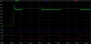
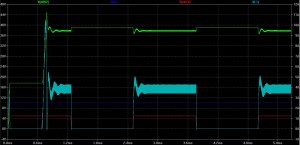
In this graph we see the voltage at the point above R4 (the sense resistor), which is close to what is being delivered to the LEDs. Notice that the voltage starts at roughly 15V and then shoots up to around 40V; the “on” state when the LEDs would be lit settles around 38V. When the red PWM waveform turns off, the voltage bounces up to the exact voltage (40V) the LT3755 is supposed to be outputting because the LEDs are not draining on the output of the circuit. When the PWM goes back on (to 5V), there is noticeable noise on the output voltage. So why is there noise?
If you look at the circuit diagram above, the second most critical component after the regulator itself is the inductor (L1), just to the upper right of the LT3755. Switchers take advantage of the fact that the voltage across an inductor is equal to the instantaneous current through an inductor times a constant (known as inductance). Pulsing current through the inductor introduces the voltages necessary to step the output voltage up to the desired level. Using negative feedback, the controlling chips can output pulses at varying speeds and shapes to correct for any errors on the output of the circuit (see the image above to see the current going through the inductor in light blue). However, as stated before, nothing is perfect. The bandwidth of the chip (the op-amps and other controlling elements within the chip) are finite, so there cannot be perfect control. This introduces noise on the output of the circuit at the same frequency as the switcher (and some harmonics of that frequency). In the LT3755, the switching frequency can be anywhere from 100 kHz to 1 MHz.
If you are using this switcher for LEDs in a car…no big deal. And really, with high power applications such as lighting, the noise isn’t much of an issue. However, as switching regulators find their way into more and more products, the noise issue becomes more prevalent, especially smaller products. The trade-off comes in when you start looking at the inductor required for the switching regulator. Some can get quite large and unwieldy, especially for handheld products (see below for an unwieldy example).

So instead of using a large value (and size and price) inductor, the switching frequency needs to increase. As explained before, voltage is created across an inductor by forcing pulses of current through the inductor. The higher frequency means that there are smaller current pulses, but there are more of them. This allows for smaller and smaller inductors in designs (some are starting to be pulled into the chip packaging!) but brings with it the noise, now at a higher frequency. If you have a 5V power supply line with 100 mV of noise of top of it (with the noise at around 100 kHz), then it might not be a problem on your circuit board. But when your boss tells you to start using smaller parts so you can fit the design in a handheld form factor and the switching frequency goes up to 1 and 2 MHz, you will start having problems. That innocent 100 mV from before now might couple into other board traces and introduce noise into the rest of your design. If you have any analog signals that are critical to your design, 100 mV of noise can wreak havoc on the output.
Less noise, more answers
Switching noise is something that will be apparent in any design involving a switching regulator. Knowing your system constraints will allow you to best decide which option is best for your specific needs. If you are crunched for space, you will need to be able to handle high frequency switching noise. If you are sensitive to noise, you better buck up for some big, expensive inductors and carefully route your board (in fact, if you’re that sensitive, maybe reconsider switching regulators entirely). If you have access to the resource, the best people to ask are the vendors selling the parts; they know the funny behavior of a part and which “flavor” of regulator to use to best suit your needs. And in the meantime you can play around with the tools they make available online and in software.
Please leave any questions or comments you might have and good luck with your new designs!


15 replies on “Switching Regulators and Switching Noise”
100mV supply noise is the bane of my existence 😛
Interesting circuit. I’ve built a DC to DC boost circuit before, but it was inductorless.
From what I can see, it would appear that the switching noise is caused mainly by the off-chip half wave rectifier rather than the chip itself. Assuming infinite bandwidth in both the chip and the power mosfet (Q1), the requirement for a more-or-less fixed output voltage necessarily caps the maximum di/dt that can be delivered to the inductor and thus, the maximum operating frequency of the switcher.
Half wave rectifiers by its very nature produces supply noise at the frequency of its input wavform. Since the maximum operating frequency of the switcher is limited to an upper bound, the output supply voltage will necessarily sag during the time when it is not rectifying, producing supply noise.
To decrease supply noise, increasing C2 can help if it doesn’t cause the feedback loop to become unstable.
Of course, I reserve the right to be completely wrong.
As someone brought up on CMOS logic (40xx), I regard static and inductance as the axis of evil still and thus I am forced to regard switch-mode supplies as more-or-less magic. Though with all these single-chip designs I should just just get on with it and play around a bit and gain some confidence with Ol’ Henry and his works.
BTW, I didn’t understand your comment “And really, the power efficiency isn’t just the garbage everyone seems to be spewing these days about saving energy for savings sake…” Could you do that again with shorter words for me?
Rgds
Damon
Hey Damon,
What I meant was that people seem to be advertising energy efficiency these days just for the sake of saying they are energy efficient. If my DVD player consumes 1W of energy and they cut it back to consuming 900mW, you know the manufacturer will say “Now super effiecient! No longer feel guilty for watching that DVD collection!”. What I was trying to say here was that the efficiency of a regulator matters because in comparison to a linear regulator, it can really make a difference. If you have a 5V, 2A supply (10 W) and are trying to make a 2.5V, 4A supply (for some super awesome processor that needs a lot of juice), having good efficiency matters more because it’s not just the overall product that is saving power, it’s the conversion of power that is now taking up less. I think power conversion is something that most people don’t think about taking up power (because people are used to transformers), so when a product can efficiently convert power, it helps. Maybe this was a bad example overall, but it was mostly my way of saying how I dislike “green-washing” and that advertisers are starting to get on my nerves. Thanks for the comment!
Chris
I’m with you against the green-washing, indeed.
Rgds
Damon
[…] of what you are buying. From an analog engineering perspective, I think of this as buying a switching converter or something similar. Sure, you know you need to change the voltage supplied to a part of a […]
Hi, sorry to be anal but the voltage across an inductor is proportional to the change in current through it. So I don’t know if it is really appropriate to say that current is being pulsed through the inductor (it can’t change instantaneously). The switch instantaneously changes the voltage polarity across the inductor so it stores energy (switch on) or releases energy to the load (switch off). The chip determines how long the inductor needs to be “charging” appose delivering current to the load. Still though, this is more of a technical detail and I enjoyed the article. I have seen issues where EMI from the switcher has interfered with sensitive analog/RF components.
[…] kinds of signals when working on just about any electronics these days. A simple example is in a switching regulator. These devices are meant to take input power from a wall plug or something providing a relatively […]
Hi, this article gives a good overview, i should have read it two years ago…
Another thing that causes noise is the shape the MOSFET performs when
switching the current.
The faster the MOSFET switches the more harmonics it will cause, but the advance of switching fast ist to save power or the necessity of cooling your transistor.
Switching the transistor fast may result in really severe radiation of high frequency noise at frequencies you might not expect (harmonics). Because the coupling path for higher harmonic might be better than for lower harmonics, it is possible that the higher harmonics (with less power) cause more radiation. The reason are the little antennas that are formed by your current path.
So one of the most important things is your layout, keep it small and (!!!) keep
the current loops small.
regards
wuifal
Hi,
I have problem with switching noise. Every time MOSFET on and off, there is an overshoot wave of 1V. Now I am trying to step down 17V to 5V. My switching frequency is 133KHz. As I said, overshoot wave 1V synchronize with noises on 5V supply line on top of 100mV noise itself. This noise give problems to my circuit which using that 5V supply. So now according to your article my understanding is if I increase the switching frequency, that might solve the problem? I will try that. By the way I am using 390uH inductor.
Hi,
I am facing a problem ,i have used lm22680 for converting 12V to 5v and its getting heated up and voltage starts falling down as i connect my video transmit section to the supply.I am also using the %v o/p to generate -5V.can some one help me out.
[…] Control — Wait a second, how do they do that when they are not a part of the switching regulator or linear regulator? Nor does the regulator have any control lines with SPI or I2C or similar? LT […]
[…] something like, ”Wow, I’d never use that”. I mean, where is the fun in using a power switcher that is damn near […]
[…] working on a new switcher design and need to be able to test the total current coming out of a boost converter. Here’s what […]
Hi, there.
I have a LED string of 16 chips are connected in serial.
I Tested the LED module which connected to LM3755 evaluation board. And I found the output voltage is 56Volts and the Current is 350 mA.
What is long with the LED Module? The LED’s If is 700ma, Vf i 3.7 Volts(Typ.).
Thanks,
David Sau