Categories
Analog Electronics Learning Renewable Energy

Switching Regulators and Switching Noise

A background

Switching regulator, buck converter, boost converter, SEPIC, flyback, push-pull, buck-boost… do you know what the heck these things are??? Because I sure didn’t when I was getting back into analog electronics. Now thanks to new interest in power efficient electronics, they are starting to come front and center on the electronics stage. Hopefully this article will give you a better understanding of what they are, what they do, where to use them and issues with noise.

OK, so before we get to the real topic of this post, what do switching regulators do?

Switching  regulators allow you to translate one voltage into another. They allow you to take a higher voltage and translate it to a lower voltage or a lower voltage and go to a higher voltage.

“Eureka!” you cry, “Chris has found the solution to all of our energy needs! We just hook a bunch of these switching doo-dads up and we’ll have unlimited power!”

But no, it’s not that easy. Switching regulators go off the fact that you can take a voltage and translate it to a different voltage, however, the power stays the same (in an ideal case). Meaning if you have 5V coming into a circuit and you have a portion of that circuit that needs to operate off of a 15V supply, you can use a boost converter or something similar and crank up the voltage. Say you have 150 mA (at 5V) coming in, when you convert it up to 15 V, you’ll have 50 mA available to whatever needs the 15V power. Notice in this (ideal) case, the power stays the same (750 mW).

It is a similar story when going down  in voltage. However, there are many more options when moving down in voltage: switching regulator, linear regulator or even a passive element (like a resistor or a diode). You use a switching regulator because they regulate the output voltage (unlike the voltage drop across a resistor or a diode) and they don’t waste power like a linear regulator. If you want to go from a 20 V input down to a 5V output, a linear regulator would just “burn” up that 15V in the middle. With a switching regulator, most of the power is conserved (assuming you are running in the optimized voltage ranges…and there are a ton of different models to choose from so you can find the right range).

Finally, real quick, where are these used? Well, the hot new talk of the town has been renewable energy. “I can get 95% efficiency?” you ask, “Why wouldn’t I pay $4 per chip to do that?”. And really, the power efficiency isn’t just the garbage everyone seems to be spewing these days about saving energy for savings sake…it actually can help you make a better product. If you are in a heat sensitive situation, you don’t want to use a linear regulator to get your required voltage. In the above example if you are going from 100 mA at 20V and the output of the linear regulator is 100mA at 5V…that means you are burning 1.5W just regulating your voltages. With a switching regulator you can save a good percentage of that (for battery or “green” devices) and you can reduce the heat in a sensitive application. Plus, if you’re trying to go from a lower voltage to a higher voltage, you’re out of luck with linear regulators.

Switching Noise

Nothing in life is perfect. Switching regulators aren’t 100% efficient, there are limits to how much you can convert voltages (1000v down to 10V usually isn’t possible…or smart) and even in the best cases a switching regulator will introduce noise into a circuit. For the ways I have mostly used switching regulators (supplies for digital circuits), switching noise isn’t that big of a deal. If you are supplying 5V to a piece of flash memory, the part will probably not care if there is 100 mV of noise “on top” of the 5V signal (meaning the actual power supplied would bounce between 4.9V and 5.1V). Same for supplying power to LEDs or other non-analog situations. However, if there are any measurement components in your design or any even slightly sensitive analog portions, you should consider how the switching noise will affect your output.

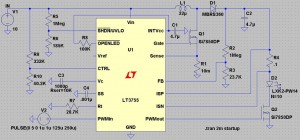
So why does switching noise occur? To answer that we really need to look at a switching regulator to understand what is inside of it. To illustrate, I will be using my version of LTSpice, which is free (awesome!). Also to note, there are lots of great programs out there to help you design this stuff (Webench, for example). Just don’t want to leave any of the vendors out, especially when they give out sampled parts. For this example, we’ll look at the LT3755, which EDN (and me by extension) showcased in an article about creating simple LED lighting for your home.  The application here would be to boost an input of 10V to an output of 40V to light an array of up to 14 1A LEDs.

lt3755

Notice the LEDs (D2 in the diagram) are where the final current and voltage is being delivered. The waveform for the inputs and outputs is below:

lt3755_chart_no_i

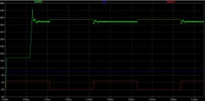
In this graph we see the voltage at the point above R4 (the sense resistor), which is close to what is being delivered to the LEDs. Notice that the voltage starts at roughly 15V and then shoots up to around 40V; the “on” state when the LEDs would be lit settles around 38V. When the red PWM waveform turns off, the voltage bounces up to the exact voltage (40V) the LT3755 is supposed to be outputting because the LEDs are not draining on the output of the circuit. When the PWM goes back on (to 5V), there is noticeable noise on the output voltage. So why is there noise?

lt3755_chart

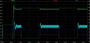
If you look at the circuit diagram above, the second most critical component after the regulator itself is the inductor (L1), just to the upper right of the LT3755. Switchers take advantage of the fact that the voltage across an inductor is equal to the instantaneous current through an inductor times a constant (known as inductance). Pulsing current through the inductor introduces the voltages necessary to step the output voltage up to the desired level. Using negative feedback, the controlling chips can output pulses at varying speeds and shapes to correct for any errors on the output of the circuit (see the image above to see the current going through the inductor in light blue). However, as stated before, nothing is perfect. The bandwidth of the chip (the op-amps and other controlling elements within the chip) are finite, so there cannot be perfect control. This introduces noise on the output of the circuit at the same frequency as the switcher (and some harmonics of that frequency).  In the LT3755, the switching frequency can be anywhere from 100 kHz to 1 MHz.

If you are using this switcher for LEDs in a car…no big deal. And really, with high power applications such as lighting, the noise isn’t much of an issue. However, as switching regulators find their way into more and more products, the noise issue becomes more prevalent, especially smaller products. The trade-off comes in when you start looking at the inductor required for the switching regulator. Some can get quite large and unwieldy, especially for handheld products (see below for an unwieldy example).

So instead of using a large value (and size and price) inductor, the switching frequency needs to increase. As explained before, voltage is created across an inductor by forcing pulses of current through the inductor. The higher frequency means that there are smaller current pulses, but there are more of them. This allows for smaller and smaller inductors in designs (some are starting to be pulled into the chip packaging!) but brings with it the noise, now at a higher frequency.  If you have a 5V power supply line with 100 mV of noise of top of it (with the noise at around 100 kHz), then it might not be a problem on your circuit board. But when your boss tells you to start using smaller parts so you can fit the design in a handheld form factor and the switching frequency goes up to 1 and 2 MHz, you will start having problems. That innocent 100 mV from before now might couple into other board traces and introduce noise into the rest of your design. If you have any analog signals that are critical to your design, 100 mV of noise can wreak havoc on the output.

Less noise, more answers

Switching noise is something that will be apparent in any design involving a switching regulator. Knowing your system constraints will allow you to best decide which option is best for your specific needs. If you are crunched for space, you will need to be able to handle high frequency switching noise. If you are sensitive to noise, you better buck up for some big, expensive inductors and carefully route your board (in fact, if you’re that sensitive, maybe reconsider switching regulators entirely). If you have access to the resource, the best people to ask are the vendors selling the parts; they know the funny behavior of a part and which “flavor” of regulator to use to best suit your needs. And in the meantime you can play around with the tools they make available online and in software.

Please leave any questions or comments you might have and good luck with your new designs!

Categories
Analog Electronics Digital Electronics Engineering Renewable Energy

Power Saving Techniques

Two things will make people want to use less power: not giving them much to start with and making it prohibitively expensive. Both of these scenarios seem to be dovetailing right now with the shrinking of many devices and energy becoming an ever more expensive and sought after.

Sure, there are people out there trying to create and harvest more energy. Either through more drilling, more wars, more acquisitions or new technologies. But eventually, people start to question why we are using so much energy in the first place. Instead of running device batteries into the ground quickly, why not draw less current? Instead of putting a bigger more expensive battery on a device in the first place, why not come up with new techniques to conserve power? Instead of paying high prices for energy and polluting the environment, why not conserve energy in our devices so that we don’t need as much energy overall?

Here are some of the methods that designers use in increasing numbers to reduce power consumption

  1. New chips — The basic idea is the same for any chip: Try and have the same or better performance of today’s chips with incrementally less power.  Most often, the best way to do so is to reduce the number of electrons it takes to store a value or drive another circuit (or whatever your task may be). However, there is a lower limit to how few electrons are required to complete a task (one, duh). How do we get less electrons doing these tasks?
    • Smaller geometries — Moore’s law tells us that process technologies will allow a doubling of technological ability every 18 months. This could even be a faster rate than previously thought, according to one of my favorite futurists, Ray Kurzweil. As fabrication facilities race to leapfrog one another to the next smallest process technology, they also help to reduce the number of electrons running through a device. If you look at the path of an electron along a trace on a microchip or op amp, it resembles a “tunnel” that electrons flow through. As process technologies get smaller and smaller (32 nm, anyone?) there is less room for electrons to flow through and thus, less power is used.
    • New materials — If you have less electrons flowing through a semiconductor, that means the total current flowing through the semiconductor is lower (current is defined as the number of electrons [measured in charge] flowing past a point for a period of time i.e. Coulombs per second). While less current can also mean less noise (fewer electrons bumping into other molecules and heating them up), it also means that if there is more resistance in a connection between two points, it will be harder for the electrons to travel that distance. As such, semiconductors are now made with new doping compounds (the molecules they force into silicon) or they forgo the silicon and try entirely new materials (Gallium Arsenide is a good example). These new materials allow for more efficient transistors and lower power consumption in devices.
    • New architectures — National Semiconductor has been pushing a new, more consistent power metric called “PowerWise“; it is targeted towards the mobile market and the “green revolution”. While this is a bit of a marketing move, it also helps to highlight their most efficient products across the different product types (LDOs vs Switching Regulators vs Op amps, etc).  Some of these newer, higher effeciency products use new architectures, as in the case of some of the switching regulators
    • Lower supply voltages — This one affects me on a more regular basis. Sure, the lower potential across a junction will drive less current in the off state (Iq) and will have less noise due to lower potentials; but this also throws a wrench in the works if you’re trying to find parts that will drive some significant currents or have any kind of large allowable input voltage ranges to a circuit without bootstrapping the supplies.
  2. PWM — Pulse Width Modulation (or PWM) is an easy way to reduce power in LED lighting situations. The idea is based off the fact that the human eye cannot determine the continuity of a light signal if it is below a certain frequency; instead, pulsing an LED on and off quickly will translate to the human eye as a lower intensity than an LED lit continuously. This idea is used regularly in portable electronics to dim the “backlight” of a laptop screen, cell phone, GPS device, etc. The duty cycle is the time that a device is powered divided by the total time it is on; usually it is given as a percentage. So if an LED is lit for 1 seconds and then off for 3 seconds (1 second on divided by 4 seconds total), the duty cycle is 25. In that example, the LED would appear to be one quarter as bright as a fully powered LED, but will also save a little less than 75% of the power normally required. The power saved can never be the entire difference between the normal case and the PWM case because some amount of power is required in order to switch between the on and off states.
  3. Microcontroller/Code Improvements — One of my favorite new blogs, written by Rick Zarr of National Semiconductor, has two great posts about the energy content of software. In it, he points out some of the ways that software can intelligently shut down portions of the code in order to reduce redundant processes and save on processing power. However, the points that I really like are the ones  he makes about making the simplest possible solution that will still get the job done well. This could mean cutting out some software libraries that were easier to just include in a project or learning how to properly construct a software project. Other techniques could be a combination of better coding and PWM: putting a device to “sleep” for a set period of time only to have it wake up at set intervals to see if it is needed.
  4. Going Analog — One last great point that Rick makes in his first post about energy saving techniques in software actually relates more to hardware. Instead of using a DSP, an ADC and some coded FIR filters, why not pull the filter back into the analog domain? Sure, it’s a little more difficult at the beginning but there won’t be any quantization errors (the error that comes from approximating a real signal with a digital signal). Analog engineers can do the same task with an active filter as digital engineers can do with a digital filter for many simpler applications. With the lower part count and the lower strain on the system of not converting a signal from analog to digital and back again, designers can save some significant power.

The final solution to our energy problems will be a combination of power saving techniques and new renewable energy sources. With some of the above techniques, designers will be able to use smaller batteries that allow longer usage times and have less of an impact on the environment. Please feel free to leave comments or any other power saving techniques you have heard of in the comments!

Categories
Analog Electronics Learning

Great resources for learning about analog electronics

I am absolutely floored by the internet every single day. I often wonder to myself if given the proper linking, guidance and mentoring, whether schools are even necessary any more (maybe the different methods are exactly what we need). This would of course also require some strong drive to learn and a whole lot of time on your hands, not to mention eyes that can bear reading computers screens all day. But I think it is possible; Some schools have even offered up their entire course catalogs online.

Me? I’m an information glutton. I will get 10 books from the library just because I get so excited about them, even if I only have time to read 2. As such, I thought I would clue everyone in to the absolute wealth of information on analog technology on the web. Most of the information you are going to find will be in the form of application notes (basically a cookbook on how to use a particular circuit). But sometimes you will find actual courses and training. I’ll be sure to list these first.  If you know of any other great resources, please leave them in the comments section! Enjoy!

National Semiconductor – The Analog University. Forget saving the best for last, this is by far the best resource I have found to date. There are full length courses that would make MIT blush.

Texas Instruments – This site has information on the entire spectrum of design from learning a concept, picking parts, creating the design and then simulating it.

Linear Technology (link 2) – These are app and design notes from one of the more robust companies out there.  There are also some great articles, some by none other than the great Jim Williams. See other work by Jim here.

Analog Devices (link 2) (link 3) – Analog devices is a monster supplier and has a lot of resources at their disposal. This allows for some great learning content. The links listed include the AnalogDialogue, a nice forum for analog discussion.

Here are some others with mostly app notes, but don’t discount them:

Maxim Semiconductor

ON Semi

Silicon Labs

NXP Semiconductor (formerly Philips Semiconductor)

That’s all I have for now in terms of online resources. I think I’ve maybe gone through about 2% of everything available, so I’ve got some reading to do!

On a side note, I’d like to welcome readers from the Motley Fool! Thanks for coming and feel free to take a look around!