Categories
Analog Electronics Learning Renewable Energy

Switching Regulators and Switching Noise

A background

Switching regulator, buck converter, boost converter, SEPIC, flyback, push-pull, buck-boost… do you know what the heck these things are??? Because I sure didn’t when I was getting back into analog electronics. Now thanks to new interest in power efficient electronics, they are starting to come front and center on the electronics stage. Hopefully this article will give you a better understanding of what they are, what they do, where to use them and issues with noise.

OK, so before we get to the real topic of this post, what do switching regulators do?

Switching  regulators allow you to translate one voltage into another. They allow you to take a higher voltage and translate it to a lower voltage or a lower voltage and go to a higher voltage.

“Eureka!” you cry, “Chris has found the solution to all of our energy needs! We just hook a bunch of these switching doo-dads up and we’ll have unlimited power!”

But no, it’s not that easy. Switching regulators go off the fact that you can take a voltage and translate it to a different voltage, however, the power stays the same (in an ideal case). Meaning if you have 5V coming into a circuit and you have a portion of that circuit that needs to operate off of a 15V supply, you can use a boost converter or something similar and crank up the voltage. Say you have 150 mA (at 5V) coming in, when you convert it up to 15 V, you’ll have 50 mA available to whatever needs the 15V power. Notice in this (ideal) case, the power stays the same (750 mW).

It is a similar story when going down  in voltage. However, there are many more options when moving down in voltage: switching regulator, linear regulator or even a passive element (like a resistor or a diode). You use a switching regulator because they regulate the output voltage (unlike the voltage drop across a resistor or a diode) and they don’t waste power like a linear regulator. If you want to go from a 20 V input down to a 5V output, a linear regulator would just “burn” up that 15V in the middle. With a switching regulator, most of the power is conserved (assuming you are running in the optimized voltage ranges…and there are a ton of different models to choose from so you can find the right range).

Finally, real quick, where are these used? Well, the hot new talk of the town has been renewable energy. “I can get 95% efficiency?” you ask, “Why wouldn’t I pay $4 per chip to do that?”. And really, the power efficiency isn’t just the garbage everyone seems to be spewing these days about saving energy for savings sake…it actually can help you make a better product. If you are in a heat sensitive situation, you don’t want to use a linear regulator to get your required voltage. In the above example if you are going from 100 mA at 20V and the output of the linear regulator is 100mA at 5V…that means you are burning 1.5W just regulating your voltages. With a switching regulator you can save a good percentage of that (for battery or “green” devices) and you can reduce the heat in a sensitive application. Plus, if you’re trying to go from a lower voltage to a higher voltage, you’re out of luck with linear regulators.

Switching Noise

Nothing in life is perfect. Switching regulators aren’t 100% efficient, there are limits to how much you can convert voltages (1000v down to 10V usually isn’t possible…or smart) and even in the best cases a switching regulator will introduce noise into a circuit. For the ways I have mostly used switching regulators (supplies for digital circuits), switching noise isn’t that big of a deal. If you are supplying 5V to a piece of flash memory, the part will probably not care if there is 100 mV of noise “on top” of the 5V signal (meaning the actual power supplied would bounce between 4.9V and 5.1V). Same for supplying power to LEDs or other non-analog situations. However, if there are any measurement components in your design or any even slightly sensitive analog portions, you should consider how the switching noise will affect your output.

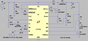
So why does switching noise occur? To answer that we really need to look at a switching regulator to understand what is inside of it. To illustrate, I will be using my version of LTSpice, which is free (awesome!). Also to note, there are lots of great programs out there to help you design this stuff (Webench, for example). Just don’t want to leave any of the vendors out, especially when they give out sampled parts. For this example, we’ll look at the LT3755, which EDN (and me by extension) showcased in an article about creating simple LED lighting for your home.  The application here would be to boost an input of 10V to an output of 40V to light an array of up to 14 1A LEDs.

lt3755

Notice the LEDs (D2 in the diagram) are where the final current and voltage is being delivered. The waveform for the inputs and outputs is below:

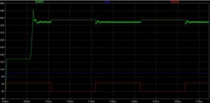
lt3755_chart_no_i

In this graph we see the voltage at the point above R4 (the sense resistor), which is close to what is being delivered to the LEDs. Notice that the voltage starts at roughly 15V and then shoots up to around 40V; the “on” state when the LEDs would be lit settles around 38V. When the red PWM waveform turns off, the voltage bounces up to the exact voltage (40V) the LT3755 is supposed to be outputting because the LEDs are not draining on the output of the circuit. When the PWM goes back on (to 5V), there is noticeable noise on the output voltage. So why is there noise?

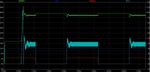
lt3755_chart

If you look at the circuit diagram above, the second most critical component after the regulator itself is the inductor (L1), just to the upper right of the LT3755. Switchers take advantage of the fact that the voltage across an inductor is equal to the instantaneous current through an inductor times a constant (known as inductance). Pulsing current through the inductor introduces the voltages necessary to step the output voltage up to the desired level. Using negative feedback, the controlling chips can output pulses at varying speeds and shapes to correct for any errors on the output of the circuit (see the image above to see the current going through the inductor in light blue). However, as stated before, nothing is perfect. The bandwidth of the chip (the op-amps and other controlling elements within the chip) are finite, so there cannot be perfect control. This introduces noise on the output of the circuit at the same frequency as the switcher (and some harmonics of that frequency).  In the LT3755, the switching frequency can be anywhere from 100 kHz to 1 MHz.

If you are using this switcher for LEDs in a car…no big deal. And really, with high power applications such as lighting, the noise isn’t much of an issue. However, as switching regulators find their way into more and more products, the noise issue becomes more prevalent, especially smaller products. The trade-off comes in when you start looking at the inductor required for the switching regulator. Some can get quite large and unwieldy, especially for handheld products (see below for an unwieldy example).

So instead of using a large value (and size and price) inductor, the switching frequency needs to increase. As explained before, voltage is created across an inductor by forcing pulses of current through the inductor. The higher frequency means that there are smaller current pulses, but there are more of them. This allows for smaller and smaller inductors in designs (some are starting to be pulled into the chip packaging!) but brings with it the noise, now at a higher frequency.  If you have a 5V power supply line with 100 mV of noise of top of it (with the noise at around 100 kHz), then it might not be a problem on your circuit board. But when your boss tells you to start using smaller parts so you can fit the design in a handheld form factor and the switching frequency goes up to 1 and 2 MHz, you will start having problems. That innocent 100 mV from before now might couple into other board traces and introduce noise into the rest of your design. If you have any analog signals that are critical to your design, 100 mV of noise can wreak havoc on the output.

Less noise, more answers

Switching noise is something that will be apparent in any design involving a switching regulator. Knowing your system constraints will allow you to best decide which option is best for your specific needs. If you are crunched for space, you will need to be able to handle high frequency switching noise. If you are sensitive to noise, you better buck up for some big, expensive inductors and carefully route your board (in fact, if you’re that sensitive, maybe reconsider switching regulators entirely). If you have access to the resource, the best people to ask are the vendors selling the parts; they know the funny behavior of a part and which “flavor” of regulator to use to best suit your needs. And in the meantime you can play around with the tools they make available online and in software.

Please leave any questions or comments you might have and good luck with your new designs!

Categories
Analog Electronics Learning

Best Free SPICE Program

One of the biggest conflicts of interest in the life of an analog engineer is that the best tool available to them is on a computer. SPICE is a program that was originally developed at Berkley to model silicon level physics to help prototyping (similar to “bread-boarding”) before the final product was produced. While it still remains a valuable tool for chip designers, it has also been broadened in scope and size to include larger designs and higher level models since it was first created. The idea is the same, that electrons basically move in the same way and that potentials in a circuit (voltages) can induce a certain behavior. So as long as the models for high level components (say an op amp or a buck converter) are well thought out, they often can represent the real world equivalent quite well.

I have some experience with SPICE and it is very helpful for both creation of new circuits and analyzing existing circuits for weaknesses.  And since I have started using it, I have tried many different versions and deviations on the original SPICE program, but I have found I like LTSpice the best. Best of all, it’s free. Like, really free. Even if you don’t know anything about circuits (analog or otherwise) and only plan to use the program once, it doesn’t matter!

LTSPICE IV — Free download! (not sponsored, I just really like the free-ness of the program)

I’m going to try my best to resist making this post sound like a puff piece, but I’ve only recently discovered LTSpice and I really enjoy how it works (even compared to similar programs that have licensing feels). The interface is the exact same as LTSpice III, so if you know that program, you won’t have much trouble with switching over to the new version.

Let’s go over some of my previous complaints about the program and how they have been been put to rest:

  1. No central area to enter model information — One of the things I had enjoyed most about the SPICE programs I had used previously was that there was a central location to put all of your model files for any models of components you might have had. Then when you were ready to use DXYZ123 in your schematic, you just match the component type (Diode, Transistor, etc) and then name it the same as your text file. In LTSpice, you have to enter the model information on the front page as a SPICE directive. While this is similar to putting the models in a separate file, if you plan on using a lot of non-LT parts in your design, your schematic can get quite cluttered.
  2. Harder to create high level schematics — OK, this was really me. I was used to different hot keys in order to modify the schematic. Really this was my impatience at learning a new system, but once I did, it’s not too bad entering new information.
  3. Only Linear Tech component models — While this is a bit annoying, it is also quite understandable since they are giving you a complex SPICE modeling program for free. There are some common passive components throughout, and you can add to libraries to add even more passives, but once you get into active parts, they are exclusively LT. See point number 1 above in order to add models for Analog Devices, National Instruments, Maxim, etc parts.

OK, enough of the downsides, let’s go over what I think sets LTSpice apart from its more expensive competition:

  1. Power consumption calculation — Hold down the alt key and on any component in your schematic and you can map the power consumption on the simulation graph (see below). This equation can be quite complicated, especially for the models that are included for all of the LT parts. As power saving techniques become more and more important to electronics manufacturers, this feature becomes indispensable. If you’re not too big on efficiency but happen to care about temperature, this same feature can estimate how much energy (still in Watts) the individual components will emit based on the power dissipated. At the very least, even if the simulation is not exact in how much power is burned during processing of a circuit, you can graph the rates of all power consumption and see which is the biggest consumer and try to optimize that part.
  2. Efficiency calculation — Again, this will become more and more important to engineers as the focus on simple fixes in products for energy efficiency becomes more prevalent. Here you have to name the input and output signals specific nodal names, but once you do, the program will automatically calculate how much energy is being converted into useable energy and how much is being wasted. An example would be in a circuit made to regulate 10V down to 5V. This can be done with efficiencies up to 90%, but some amount of energy will be dissipated by resistors or active components like op-amps. Ya gotta spend energy to make energy.
  3. Dual Core integration — This is one of the biggest improvements from LTSpice III (really it was called SwitcherCAD III) to LTSpice IV. Now they have support for dual core processors which are quickly becoming the standard in computers from desktop to laptop to netbooks (OK, not yet on netbooks). Either way, if you are only using one available core for your simulations, you’re running at roughly half of what they COULD be running at. I have a dual core on my current machine and LTSpice quickly used up the available resources and the quickness of results showed the difference. LT is still working on the bugs on some types of computers processors, so they only run on one core, but hopefully it will be functional on all types of machines soon.
  4. Graphing function — This isn’t any different from LTSpice III, I just thought I should mention how much I like the graphing abilities of this program as compared to others I’ve used. LTSpice really grabs hold of the graphic model in SPICE and runs with it; their software allows you to click on a node to find out the voltage (even after the simulation is completed) or to click on a particular component to find out how much current has gone through that part throughout the simulation. The point and click method allows for quick diagnosis of problem components and circuit layouts.

  5. Dynamic Simulation — Linear Tech is a big player in the switcher market (a switcher basically takes input power and pulses an output–usually through a capacitor or inductor–to produce a stable output). However, the side result is that their program is well suited to handle rapidly changing inputs. I plan to re-construct my Wurlitzer 200A schematic in LTSpice in order to better understand some of the parameters affecting the sound and maybe even inputting and outputting sound files (you can do that with raw formats). More on that in later posts.

All and all, I know I sound like I’m gushing, but I always enjoy free software that is made well. It’s like some of the open source programs I love, but with a company behind the product supporting it (and yes, trying to sell you chips).  There are many other great SPICE programs out there and some of very worth the fees they charge. However, if you are looking for a quality program at no cost, I would suggest LTSpice.

Do you know of other SPICE programs? Do you like them better for one reason or another? Please let me know in the comments section.

[xyz_lbx_default_code]

Categories
Analog Electronics Music Renewable Energy Supply Chain

Keep it simple, stupid

Keep it simple, stupid

The KISS principle is pertinent in nearly every aspect of my life. I can’t begin to relay the number of times I have had to convince myself to step back from a situation–engineering or otherwise–and ask what the simplest solution is. Be it electronics at work or at home, renewable energy or even my investing, I encounter the KISS principle over and over again.

A tenet of the ever-expanding chip market is that the more functions that were once done with discrete components and can now be moved into the confines of a chip, the better. This is done either directly on silicon or by setting multiple pieces of silicon next to each other in the plastic packaging and wiring them together. This idea started a long time ago but is being to manifests itself in many different ways. One of the earliest examples is the op-amp. True, the form and function of the op-amp is different than the cascodes and the vacuum tubes that preceded it; but the idea of bringing the capacitor (to control the slew rate) and the transistors required to drive the differential inputs and the output all into the same package were just the first examples of combining discrete elements into an easily re-usable device was new. Another driving force was the idea that this device can be mass produced and sold at a lower cost thanks to economies of scale. More recently we have seen more and more functions brought into the chip packaging. One such example is the FPGA, which not only reduces the need for external logic gates in some bulky package, but it also makes it reconfigurable. And now, predictably enough, this same concept is being brought into play with analog! There are now chip manufacturers that make Field Programmable Analog Arrays (FPAA). Usually this consists of an op-amp, some analog switches and passive components, such as resistors and capacitors (for filtering). The device can be “programmed” to select any number of functions, with the potential for ever increasing complexity (though signal integrity would be a concern of mine). The final example is a product offering called the uModule from Linear Technology, with others doing similar things. It is an interesting concept because they are bringing in even more discrete components, such as inductors on a DC-DC converter; inductors are typically set outside the chip because of size concerns.

So how do these complicated chips affect designers and end users? They make things simpler (in theory). Open any modern day cell phone or look at a tear down, and you will see very little on the board in terms of discrete components (granted, this is also for space concerns). But chips that have everything included really do make everything simpler. Sometimes they are drop in solutions, such as with the uModule. All you need to do is determine the DC to DC conversion you want and then populate the board with their chip and two capacitors. On cell phones, there is usually 1 chip for each type of communication protocol (WiFi, CDMA, etc). If and when FPAAs ever become popular, they will only require that you populate a board with them, route the proper signals and then program what kind of filtering and amplification you want. This could even be as simple as saying what knee frequency you require and if you are particularly sensitive to ripple in the passband or stopband. Then the chip would know to use a butterworth, chebyshev, bessel, etc to get your desired results. The main point is, more and more people will be able to design systems, because the chip makers are paying attention to the minutiae (for a price, of course). This then allows fewer designers to make more designs, faster. Companies love the sound of that, because then they get more bang for their buck. As an aspiring futurist, I would even venture a guess that the system designers of tomorrow will really be software people with a knack for picking out parts. They will know what they need each part of the design to do and then will go through a catalog that will do it.

OK, so aside from using systems on a chip and not bothering to design systems when I can buy them, how else do I keep it simple? Well, a burgeoning hobby of mine is vintage analog electronics. Really I bought a 1968 Wurlitzer 200A electric piano on a whim and decided to fix it up/learn how to play it. The latter of those two goals is too lofty in the near term and shan’t be discussed here; however, the former of those goals has presented some good lessons from pulling this fine piece of equipment apart. When I first opened it and saw the components, I decided right away that I would  be redesigning everything, including a new circuit board and using the most efficient new parts. However, as I’ve dug into the design I’ve found that not only would this be silly, it could be detrimental. One of the best things about vintage audio electronics is the intangible “warm” sound they often have. This could be from using vacuum tubes or just noisy components that were designed to create the best sound they could at the time. If I replaced everything, I would lose the natural sound of the instrument, basically rendering it useless (in terms of re-sale and in terms of playability). Instead, the simplest course of action is to replace the dried out capacitors with the closest match I can and leaving everything else alone. Simplicity wins again!

Renewable energy, specifically solar, has begun taking the KISS principle to a new level. Solar panels are not yet cheap or abundant as we want and need them to be. But mirrors are! So why not take a really simple method of essentially putting mirrors on a parabolic dish and then pointing it at a water tower? This simple approach then forces the steam through a turbine and voila, electricity. Now create a project that does this many times over, in a desert no less, and you have a serious contender for long term energy independence.

“The best way to own common stocks is through an index fund.”–Warren Buffett…The best investor in the world and one of my personal heroes, says this about 99% of investors. Regardless of what this says about his confidence in the average (and not so average) investor, I think it is a perfect example of keeping it simple. In fact, it doesn’t really get much simpler. And history has proven it too. In 2006, a study found that only .6% of active money managers can beat the market. Keeping it simple and buying that index mutual fund will ease your mind and your wallet!

Do I follow these ideas in my life and work? Sometimes. But as I experience more and more, I find that the KISS principle is one that could bring more harmony into many different aspects of my life.

Categories
Analog Electronics Learning

Great resources for learning about analog electronics

I am absolutely floored by the internet every single day. I often wonder to myself if given the proper linking, guidance and mentoring, whether schools are even necessary any more (maybe the different methods are exactly what we need). This would of course also require some strong drive to learn and a whole lot of time on your hands, not to mention eyes that can bear reading computers screens all day. But I think it is possible; Some schools have even offered up their entire course catalogs online.

Me? I’m an information glutton. I will get 10 books from the library just because I get so excited about them, even if I only have time to read 2. As such, I thought I would clue everyone in to the absolute wealth of information on analog technology on the web. Most of the information you are going to find will be in the form of application notes (basically a cookbook on how to use a particular circuit). But sometimes you will find actual courses and training. I’ll be sure to list these first.  If you know of any other great resources, please leave them in the comments section! Enjoy!

National Semiconductor – The Analog University. Forget saving the best for last, this is by far the best resource I have found to date. There are full length courses that would make MIT blush.

Texas Instruments – This site has information on the entire spectrum of design from learning a concept, picking parts, creating the design and then simulating it.

Linear Technology (link 2) – These are app and design notes from one of the more robust companies out there.  There are also some great articles, some by none other than the great Jim Williams. See other work by Jim here.

Analog Devices (link 2) (link 3) – Analog devices is a monster supplier and has a lot of resources at their disposal. This allows for some great learning content. The links listed include the AnalogDialogue, a nice forum for analog discussion.

Here are some others with mostly app notes, but don’t discount them:

Maxim Semiconductor

ON Semi

Silicon Labs

NXP Semiconductor (formerly Philips Semiconductor)

That’s all I have for now in terms of online resources. I think I’ve maybe gone through about 2% of everything available, so I’ve got some reading to do!

On a side note, I’d like to welcome readers from the Motley Fool! Thanks for coming and feel free to take a look around!