Categories
Analog Electronics

What Is A Power Budget?

Boy is it hot in here or is it just me? Why’s that gizmo over there giving off so much heat?

Power budgets are a necessity these days. Due to increasing regulation, we’re seeing devices that must comply with efficiency limits in their power conversion (using a switching power supply or otherwise).

So what is a power budget? Much like a budget you might have for your personal finances, a power budget shows where all the possible power will be used by a device to by breaking it down into components and categories. In some situations, you might be told up front that you will have 3W available to run your design. However, sometimes as designers we start by calculating the total power a system needs and then taking actions such as replacing parts or redesigning circuits to cut back power to an acceptable level. So why might someone want to do a power budget from day one?

  1. Power availability — While you might have more power today, it doesn’t mean you’ll have it tomorrow. Designing a system for 3 W power consumption may be acceptable now, but designing a lower power system may meet future regulations. And the trends in the industry point in that direction.
  2. Battery Life — If your device is running off a battery, you likely do not have a choice whether you are doing a power budget. You want to maximize the life of your device on a single charge (assuming it is using rechargeable batteries) and your customers want the same. Just a few weeks ago I was complaining publicly on The Amp Hour about my new device with poor battery performance. Doing a power budget will point to the components consuming the most power so you can later optimize for longer battery life (hopefully this was a design constraint from the beginning).
  3. Heat generation — Heat is an unfortunate side effect of working with electronics. However,  it also has a 3 direct effects on your product and how it is used.
    1. User discomfort — No one likes having a hot laptop sitting in their lap. Nor a cell phone that is uncomfortable to hold.
    2. Circuit robustness — An often quoted specification of an op amp is the voltage offset drift. This sensitivity to temperature can have dire effects in systems that rely on analog accuracy. However temperature changes can create conditions that are unfavorable and could even cause device failure (such as thermal runaway). The heat of the whole system can end up affecting individual components as the nominal temperature inside your device rises.
    3. Product lifetime — The lifetime of a product can be drastically reduced by higher than normal temperatures inside the device. Extreme temperatures can begin to dry out capacitors and cause others to fail catastrophically. While it is possible for systems to fail in a drastic manner, the more likely outcome is a product that does not last for its specified lifetime. An example might be a TV that has a less vibrant LCD after 5 years due to excessive heat and component drift and fatigue. If the product was designed to have lower heat, the product would have lasted longer. For more on how to design and prevent early failures, check out Dave’s video blog about heatsink design.
  4. Cost (sizing) — More power means you need larger components. Other than the obvious requirement of needing more space (duh), it often correlates to higher cost components. Not only will you need larger packages for your components such as op amps and comparators in order to better dissipate heat. You’ll also need a larger power supply with more reliability. If a 5W and 20W power supply with 12V output are compared, the 5W supply has smaller magnetics and less wiring because there is less total current that needs to pass through.

So let’s look at an example power budget (click for a larger version):

As you can see, not much more is required than your datasheets and a spreadsheet type program. Even simpler is a piece of paper but I prefer the built in math functions of the spreadsheet program. The first two columns (A&B) are simply identifiers to allow you to recognize which components correspond to which set of data. The next two columns (C&D) determine the multiplicative factor. If you have 5 components that contain 4 op amps per, then that will consume 20x the power of a device that has the same supply current needs but only one op amp per and there is only one on the board.  The next two columns (E&F) show how much current each individual component contributes and then the sum of all the components of that type contribute. Note that this parameter on a data sheet would be listed as “supply current” or “active current”. The “quiescient” number is when the device is in a resting state and will likely be much less than the active number (and not relevant for this example). Finally, the supply voltage is listed (in column G) to calculate power (using the formula P=I*V) which is listed in column I per device. All of these contributors are summed, an efficiency is estimated (I assumed a poor efficiency linear type supply) and the total power required input to the device is given. Further calculations could result from much of this initial data.

I would be remiss without mentioning something about power budgets: you’re still going to guess about certain things. In fact it will be many different things. You might not have perfect data about your components. You might not completely trust the “typical spec” of one of your components. This is the point where you design in a margin of error. However, just like many other aspects of engineering, this is where tradeoffs come into play. You might want to design in 4 times more power capability than you calculate (to feel safe), but there are cost and spec requirements to consider. You will have to determine how confident you are in your design and how many resources you have available to your design. In the above example where the 5V parts require 408mA from the supply (~2W), I might over spec the part by designing in a part that is capable of supplying 600mA. The (50%) margin of error allows for future expansion (might need to solder in an extra part or two) and also gives a cushion if anything was miscalculated. In some situations this 50% might be too much (think a very low-cost, high volume design) or might be too little (think a military, high reliability design). It all depends on the situation and requirements.

Power budgets can be very powerful depending on the amount of time and effort you put into them. Otherwise they are educated guesses which may or may not be helpful to your project; how helpful they are might also depend on where you are in the design cycle. As stated before, these budgets are more and more of a necessity in a world more power conscious and with devices that continue to shrink. Your customers will expect longer battery life and your products to have yet more features. Teach yourself how to do power budgets now and it will pay dividends for you in the future.

[xyz_lbx_default_code]

Categories
Analog Electronics Engineering Work

When to Try Something vs When to Study Something

Irony is having a blog post in your queue with a title such as this one and just sitting on it for weeks on end. Luckily I’ve been trying some things instead of studying them, it just so happens that those things have nothing to do with this site. I hope to discuss those on this site soon.

I am a glutton for knowledge.  Part of it is my fear of looking silly in front of co-workers when I don’t know the answer to something. Part of it is feeling like my knowledge base is lacking and the thought that I can always learn or teach myself something new. But when presented with a new challenging situation that requires you to learn the question is always the same: where do you start? Do you jump in and try it out? Or sit back and study what others have tried so as to not duplicate their mistakes?

There are two extremes

  1. You study so much and try to take in so much that you become paralyzed by information
    • I feel like this happens to Generation Y more than other generations. Not because we are dumber than others. Instead, I think we are so accustomed to having all of the necessary knowledge required to solve a problem at our fingertips (i.e. Internet, ChrisGammell.com, etc).
    • Academic thought processes often begin with simplistic assumptions about the model you’re considering. Analyzing these over and over can be very time consuming and can quickly become too complex to handle. Even analyzing the minutiae associated with a single transistor can be mind boggling. What happens when you try and expand that knowledge to 10, 10k or 10M transistors?
    • You over simulate, over analyze, over think a problem past the point of diminishing returns. An example would be designing a new type of toothbrush. You can model the toothbrush, the bristles, the handle, the shapes, everything; you can even go out and get ideas from your toothy customers about what they think they would like or dislike about your design. But until you prototype your new type of toothbrush and put it through testing (product testing, tooth scrubbing ability, will it shatter in someone’s mouth), then all of the testing and surveying in the world won’t matter.
  2. You have little knowledge of a problem or situation that you just start changing stuff randomly and keep changing until something works…without realizing the consequences.
    • This seems to be the modus operandi of the inexperienced, but not necessarily the uneducated. A gutsy, recently graduated electrical engineer may emerge from the cocoon of the academic environment ready to go out and change the world. And every resistor value of a circuit board they encounter. And mess with the capacitors. And change the model of the op amps. Oh, and don’t forget to swap out transistors. “What?? It still doesn’t work? But why?”
    • This can be as much a symptom of engineering bravado as it is bad conditioning. If the person involved has always had simple problems placed in front of them that have obvious or at least semi-obvious solutions (ahem, most introductory electronics labs), they will fix the “broken” component and pat themselves on the back. In the real world, that “broken” component isn’t broken at all. It’s just out of spec and you can’t figure out for the life of you why that unit you’re testing refuses to turn on anymore after increasing 5 degrees internal temperature.
    • You forget/refuse to read the manual. Granted, some of the greatest “tinkerers” out there can just magically turn a knob and get a broken piece of equipment to work. But the reason they can do that is because they actually turned the wrong knob about 1000 times the last time they tried to fix something like this and that knob did absolutely nothing.

A Good Mix (for me, at least):

[STUDY] My own personal mix when it comes to circuit problems starts with the problem definition. Understanding the problem is so much more important than what you study, how long you study it or how you begin to test out your ideas for how to fix it. If you don’t understand what the real problem is all that later work is for nothing! However, I try to understand the issue without going overboard and trying to understand every single minute detail; this could be just as bad as studying a possible solution for hours on end.

[TRY] Once I have a grasp on what the problem is, I try the obvious stuff. You’d be surprised how often it can be the really dumb things that trip you up. And those might not even be the problem you’re trying to fix. You could try to troubleshoot a blank screen for 20 minutes, throwing your best ideas and debugging techniques at it before you realize, “Whoops!” you never plugged in the display cable. Or you can’t get your software to work once you load it onto your electromechanical whizzbang toy…but you actually loaded the wrong version of the software or the toy doesn’t have any batteries in it. The silly things will waste your time and throw you off the trail of the real problem if you’re not careful.

[STUDY] Next is researching the problem to see if it has happened before. Some of you out there will have unique situations, like making a new analog chip that no one has ever made before. But I’d guess more of you will be encountering problems that can be researched. Even the analog chip designers will see issues that are similar on some level to other products or models within a corporation. Oftentimes the best troubleshooters are those who are able to compartmentalize problems and then analyze where those problems came from and research how others have fixed it in the past. I’d rather have a boring problem that someone else can easily tell me how to fix than one that I can’t figure out at all.

[TRY] After trying and then studying all of the really obvious stuff, I start to go back to my resources–either online or in print–and start to search for information on the topic. Obviously the online information is much easier to search, but I also have some trusted books that I turn to on a regular basis. I might see a chunk of a circuit that looks familiar and try flipping through the pages to see if I can’t find a similar circuit. If that doesn’t work or the circuit looks extremely foreign to me, I’ll go back and study some of the basic properties of the components within the circuit to see if there might be a certain property the designer used that I have overlooked. And if all else fails, I’ll start to ask around to try and gather others’ knowledge of the circuit. True, this isn’t quite studying, but can often be more effective. I try and balance asking others for assistance only after I have tried to solve the problem on my own and not made any progress. I think it is important for my personal growth to struggle with a circuit before asking for help and I think it’s important to not get in the habit of running off and asking for an answer so I don’t waste the other person’s time. However, I don’t want to be so stubborn that I waste my time and the time of those who are paying me.

[STUDY] Alright, so now you know what the circuit is and how it sort of works. But you also know that you need to change the circuit in order to make it work better. What now? Next I would try and write out any equations I know that are relevant to the circuit. Not necessarily any equation, that could end up being a waste of time. Keep it simple and make sure you know where the currents and voltages are in different parts of the circuit. If there are components (such as capacitors) in the circuit, include basic equations that can help to describe their behavior. If you don’t need 3 chalkboards to do so, try and figure out the transfer function (relationship from input to output). If you have a circuit that is too complicated either break it down into smaller pieces and try and figure out the transfer function or take the plunge and try it out in SPICE. This will help you to better understand how the circuit might behave when presented with certain inputs. All of these exercises are done in order to present you with a solid starting ground for when you actually construct the circuit, so you know what to look for and what behaviors to expect.

[TRY] After all of the studying and simulating and pondering about this circuit, you should have at least enough knowledge to begin building up and trying the circuit. This is an important step in any circuit creation process because of the nuances the real circuit will show you. Perhaps you forgot to model a realistic op amp in your SPICE simulation and it was outputting 500 A. Perhaps you didn’t realize in your equations that a resistor will have different properties depending on how much current you actually put through it and that your circuit happens to be particularly susceptible to those changes. Perhaps you completely disregarded a simple concept such as bandwidth and your circuit is now oscillating so hard it breaks. All of these things will be uncovered when you begin to build up your circuit and try out different inputs. Once you realize what some of the realistic problems are you can go back and modify your assumptions and models and start to delve into whatever topics you believe will get your circuit to the optimum operating point.

Finding the right balance between slowing down and taking your time to figure out a circuit or jumping in and seeing what works can be a fine art. Sometimes projects are on a very tight schedule and need a product cranked out the next day (think startup). Sometimes you have one shot at making a final product or else your company will fail (think chip fabrication). Finding your own personal mix will take time and trial and error.

What is your personal mix of trying vs. studying that gets the best results? Leave your tips and tricks in the comments!

Categories
Analog Electronics Digital Electronics Engineering Learning Life Work

How to get a job as a new electrical engineer grad

I was going to call this post “A portrait of an electrical engineer as a young man (or woman)” but decided against it. I’ve got nothing on James Joyce, neither in loquaciousness nor confusing writing.

Anyway, I have been pondering what kind of employee I would hire out of school for an electrical engineering position. There are some basic skill sets that will allow just about any young engineer to succeed if they have these skills (the best situation) or at least appear they will succeed if written on their resume (not the best situation). Either way, let’s look over what a new grad should have on their utility belt before going out into the scary real world.

  1. Conceptual models of passive components — This has been one of the most helpful things I have learned since I have left school…because this kind of thinking is not taught in classrooms (at least it isn’t in the curriculum). The idea is to conceptualize what a component will do, as opposed to what the math is behind a certain component or why the physics of material in a component give it certain properties. Why does this matter? When you’re looking at a 20 page schematic of something you’ve never seen before, you don’t care what kind of dielectric is in a capacitor and how the electric field affects the impedance. Nope, you care about two things: What is the value and how does it affect the system. The first question is easy because it should be written right next to the symbolic notation. The second is different for each type of passive component you might encounter. Let’s look at the common ones
    • Resistors — The  best way I’ve found to think of resistors is like a pipe. The electrons are like water. The resistance is the opposite of how wide the pipe is (if the resistance is higher, the pipe is smaller, letting fewer electrons through in the form of current). Also, the pressure (voltage) it takes to get water (electrons, current) through a pipe (resistor) will depend on the thickness of the pipe (resistance). Well whaddaya know? V=IR!
    • Capacitors — At DC, a capacitor is essentially an open circuit (think a broken wire). If you apply charge long enough (depending on the capacitance), it can consume some of that charge; after it is charged it will once again act like an open circuit. When considering AC (varying) signals, the best way to think about a capacitor is like a variable resistor. The thing controlling how much the capacitor will resist the circuit is the frequency of the signal trying to get through the capacitor. As the frequency of the signal goes up, the resistance (here it is called “impedance”) will go down. So in the extreme case, if the frequency is super high, the capacitor will appear as though it is not there to the signal (and it will “pass right through”). Taking the opposite approach helps explain the DC case. If the signal is varying so slowly that it appears to be constant (DC), then the impedance of the capacitor will be very high (so high it appears to be a broken wire to the signal).
    • Inductors — Inductors have an opposite effect as capacitors and provide some very interesting effects when you combine them in a circuit with capacitors. In their most basic form, inductors are wires that can be formed into myriad shape but are most often seen as spirals. Inductors are “happy” when low frequency signals go through them; this means that the impedance is low at low frequencies (DC) and is high at high frequencies (AC). This makes sense to me because if the signal is going slow enough, it’s really just passing through a wire, albeit a twisty one. An interesting thing about electrons going through a wire is that when they do, they also product tiny magnetic fields around the wire (as explained by Maxwell’s Equations). When a high frequency signal tries to go through the inductor, the magnetic fields are changing very rapidly, something they intrinsically do not want. Instead it “slows” the electrons, or really increases the impedance. This “stops” higher frequency signals from passing through depending on the inductance of the inductor and the frequency of the signal applied. Looking at the how they react to different frequencies, we can see how inductors and capacitors have opposite effects at the extremes.
    • Diodes — I think of diodes as a one way mirror…except you can’t see through the one way until you get enough energy. The one way nature is useful in blocking unwanted signals, routing signals away from sensitive nodes and even limiting what part of a varying signal will “get through” the diode to the other side.
    • Transistors — I always like thinking of transistors as a variable resistor that is controlled by the gate voltage. The variable resistor doesn’t kick in until the gate voltage hits a certain threshold and sometimes the variable resistor also allows some energy to leak to one of the other terminals.
  2. C coding — Sorry to all you analog purists out there, but at some point as an engineer, you need to know how to code. Furthermore, if you’re going to learn how to code, my personal preference for languages to start with is C. Not too many other languages have been around for as long nor are they as closely tied to hardware (C is good for writing low level drivers that interpret what circuits are saying so they can talk to computers). I’m not saying higher level languages don’t have their place, but I think that C is a much better place to start because many other languages (C++, JAVA, Verilog, etc) have similar structure and can quickly be learned if you know C. Even though the learning curve is higher for C, I think it is worth it in the end and would love to see some college programs migrate back towards these kinds of languages, especially as embedded systems seem to be everywhere these days.
  3. How an op amp works — I set the op amp apart from the passives because it is an active component (duh) and because I think that it’s so much more versatile that it’s important to set it apart conceptually. I’ve always had the most luck anthropomorphizing op amps and figuring out what state they “want” to be in. Combining how you conceptually think about op amps and passives together can help to conceptualize more difficult components, such as active filters and analog to digital converters.
  4. The ability to translate an example — A skill that nearly every engineering class is teaching, with good reason. Ask yourself: are homework problems ever THAT much different from the examples in the book? No. Because they want you to recognize a technique or a idiosyncrasy in a problem, look at the accepted solution and then apply it to your current situation. Amazingly, this is one of the most useful skills learned in the classroom. Everyday engineering involves using example solutions from vendors, research done in white papers/publications and using even your old textbooks to find the most effective, and more importantly, the quickest solution to a problem.
  5. High level system design — This is similar to the first point, but the important skill here is viewing the entire picture. If you are concentrating on the gain of a single amplification stage, you may not notice that it is being used to scale a signal before it goes into an analog-to-digital converter. If you see a component or a node is grounded periodically, but ignore it, you may find out that it changes the entire nature of a circuit. The ability to separate the minutiae from the overarching purpose of a circuit is necessary to quickly diagnose circuits for repair or replication in design.
  6. Basic laws — It is amazing to me how much depth is needed in electrical engineering as opposed to breadth. You don’t need to know all of the equations in the back of your textbook. You need to know 5-10; but you need to know them so well that you could recite them and derive other things from them in your sleep. A good example would be Kirchoff’s laws. Sure, they are two (relatively) simple laws about the currents in a node and the voltage around a loop, but done millions of times and you have a fun little program called SPICE.
  7. Budgeting — There are many important budgets to consider when designing a new project. In a simple op amp circuit, there are many sources of error and inefficiencies. Determining and optimizing an error budget will ensure the most accurate output possible. Finding and determining areas that burn power unnecessarily must be discovered and then power saving techniques must be implemented. The cost is another consideration that is usually left to non-engineering, but is an important consideration in many different projects. Finding cost effective solutions to a problem (including the cost of an engineer’s time) is a skill that will make you friends in management and will help you find practical solutions to many problems.
  8. Math — Ah yes, an oldy but goody. Similar to the passive components, having a conceptual notion of what math is required and how it can be applied to real life situation is more important than the details. Often knowing that an integral function is needed is as important as knowing how to do it. And similar to the basic laws, you don’t need to know the most exotic types of math out there. I have encountered very few situations where I need to take the third derivative of a complicated natural log function; however, I have needed to convert units every single day I have been an engineer. I have needed simple arithmetic, but I’ve needed to do it quickly and correctly. Sure, you get to use a calculator in the real world, but you better learn how to use that quickly too, because your customers don’t want to wait for you to get out your calculator, let alone learn how it works.

Each of these skills could be useful in some capacity for a new electrical engineer grad. There are many different flavors of engineering and the skills listed above are really modeled off what would be good for an analog system engineer (who develop commercial or industrial products). However, a future chip designer and even a digital hardware engineer all could benefit from having the skills listed, as it is sometimes more important to be open to new opportunities (especially given the possibility of recession and potential shifting of job markets).

Did I miss anything? Do you think there are other skills that are necessary for young electrical engineers? What about general skills that could apply to all young engineers?

[xyz_lbx_default_code]

Categories
Analog Electronics Learning

How an op amp works — Part 2

As promised, this post is a follow up post to explain the real-world behavior of an op amp. Here we will continue to anthropomorphize op amps in order to better understand their behavior and what they “want” to do. Also, we will look at some more complicated (but common) op amp configurations so that they are easily recognizable. Let’s begin.

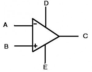
First, let’s look at the symbol for the op amp:

Whoa-ho! What the heck are those? Last time, there was only 3 lines coming out of the triangle and now there’s five! They’re multiplying!

Really the “D” and “E” inputs are the power inputs to the op amp. This means we are no longer simply dealing with the “ideal” case and are now going to look at the behavior with some realistic expectations. I know that when I was first learning about op amps, I was perplexed by this idea. I thought, “Well what is the point of putting power into an op amp? What do I get for it?” The idea is that as long as the signal at the input (or more accurately the difference between “A” and “B” is smaller than the power at the “D” and “E” terminals, then the op amp can amplify the signal. This gets very useful once you start encountering signals that change over time, or AC signals (as opposed to DC signals). Let’s look at this idea below:


Special thanks to CoolMath.com for the graphing program!

On the top left, we see a SINE wave, which is one of the simplest time varying signals there is. Amplifying this signal would not shift the signal, but instead would make the entire range of the signal larger. If we used a 4x amplification, then we would get the top right picture with the larger signal. Notice in the bottom picture the overlay of these two signals. They do not SHIFT up, but instead look like they are stretched. The easiest way to think of all this is at the extremes. If in the first picture the highest point was 1 and we had 4x amplification, then the output would be 4. However, the middle point is 0 and that multiplied by 4 is still zero. Hence the reason the overlay shows the extreme highs and lows being “stretched” the most. Also, it is important to note that these are analog signals, so EVERY point in between the extremes is being amplified.

The power coming into the op amp also restricts how much the op amp can amplify a signal. Not only that, but sometimes you don’t even get to go to the limits! Say you have +15 volts attached to “D” and -15 volts attached to “E” (most op amps have lower voltages these days but +/- 15 volts still happens sometimes). Now let’s say you have a 1V signal coming into a non-inverting amplifier (shown below). The gain on this amplifier is set to 15 by making the top resistor 14 times less than the resistor connected to the ground (non-inverting amplifiers have a gain of 1+R(top)/R(gnd)). So our 1 volt signal is placed at the non-inverting input (the plus) and the op amp says “15 volts, coming right up!”. Ah, but the op amp doesn’t quite have it. The op amp outputs 13.4 volts are so and then stops. “But WAIT!” you say, “why can’t this op amp output as much as I wanted? The ideal ones can output INFINITY. Can’t I just get one of those?” The short answer: no, you can’t. Op amps have internal protection circuitry that limits how high the input to the op amp can be in order to protect it from blowing up. Additionally, the op amp must consume some of that power in order to actually amplify the input signal; this will be expounded upon in further posts (the internals of an opamp).

The final point in this continuing discussion about op amps, is known as slew rate. Really it is a discussion of how fast an op amp can go and is limited by capacitance. Inside of any op amp, there is a capacitor, or rather a bunch of components that act together as one capacitor. This creates a required charge time for the internals of the circuit (for a more advanced look at this topic, check out the allaboutcircuits.com article on capacitors and calculus). The end result is that the op amp has some limit to how fast it can “decide” what the output should be. If we think back to the signals above that alter with time, we can imagine a situation where they would vary so quickly that an op amp would not be able to keep up. The end result is that a circuit such as the non-inverting amplifier shown above has some frequency above which it can no longer accurately amplify. This is known as the bandwidth of the circuit and has implications in many audio, measurement and communication industries.

This post discussed some of the real world aspects of op amps. The next post will discuss the internals of the op amp, such as the transistor setups. Imperfections in the silicon and the realities of material science will show us that more of the “ideal” op amp model is not possible in every day life; some potential topics are the input bias currents, the voltage offsets across the input terminals and how they can affect everyday circuits.

[xyz_lbx_default_code]

Categories
Analog Electronics Learning

How does an op amp work? How do I use an op amp? — Part 1

How does an op amp work? How do I use an op amp

These are questions that I have asked at two periods in my life. The first time was in my introductory circuits class and around that time I really didn’t care (beer was a priority). The second time was when I dove headfirst back into analog electronics for my new job and had to re-teach myself a lot of things. I really appreciate the opportunity I had to re-learn everything because the second time around, I think I got it right.

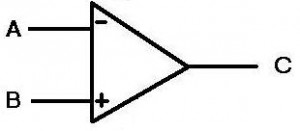
OK, so let’s start simple. What is an op amp? Whoa, loaded question. For our purposes here (and just for now), let’s say it’s just a symbol.

Figure 1: Just a symbol folks, nothing to see here

To keep things basic, the A & B points are the input, the C point is the output.This symbol is an IDEAL op-amp, meaning it is impossible to construct one and really the expectations for the op amp are unrealistic. But this is the internet and we can do what we want on the internet, so we’ll just use the IDEAL op-amp for now.

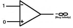
Figure 2: Inverting Ideal Op-amp

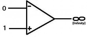
OK, so now you know what the symbol is, but what does it mean? Well, the idea is you put two electrical signals into the inputs then the output changes accordingly. It takes the difference between the inputs and amplifies it, hence operational amplifier, or op amp. You may have noticed that input A has a minus symbol and input B has a plus symbol. So let’s say that the input to the minus, or INVERTING, input is 1 (for simplicity’s sake…this site is about analog so that value could be ANYWHERE from 0 to 1 or higher! Just thought I’d mention that). The input to the plus, or NON-INVERTING, input is 0. Now the op-amp is in an unbalanced state. The device is designed so that when this happens, the output goes as negative as it can. For the ideal case, we say this is negative infinity, but that’s not really possible. More on that later.

Figure 3: Non-inverting Ideal Op-amp

Conversely, in figure 3, if we put a one on the non-inverting and a zero on the inverting input, the op amp output would go high, infinity for our purposes here. The important thing to know is this:

The op-amp always “wants” both inputs (inverting and non-inverting) to be the same value. If they are not, the same value, the op amp output will go positive or negative, depending on which input is higher than the other.
(Throughout this article I will continue to anthropomorphize op amps…best to get used to it now)

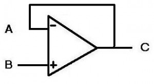
Alright, so how do we use this in circuits? If we wanted to find out if two signals were different, we could tie the signals to the inputs of the op amp, but then the output would go to infinity. This would not do us any good. The answer to this and many other questions in the universe is feedback. We are going to take the output and tie it back to the inverting input. Now the circuit looks like this:

Figure 4: A buffer
Figure 4: A buffer

First, we assume that the circuit has all points start at zero (point A being the most important). Next, we put a value of 1 (like the picture in figure 2) at the “B” non-inverting input. “WHOA,” says the op amp, “THIS AIN’T RIGHT!” So now the op amp puts its output to as high as it can, as fast as it can. This feeds back from the output (“C”) to the inverting input (“A”). So as the output moves closer to 1, the op amp is happier and backs off the output. When the input at A is the same as at B, the op amp is happy and stays there (but maintains the output of 1). The key here is that the op amp moves as fast as possible to get both inputs to be the same.

Why would someone use a buffer? Well that brings us to the next point about op amps, specifically ideal op amps:

Ideal op amps have infinite impedance (resistance) at their inputs. This means that no current will flow into the op amp.

A common use for a buffer is to supply current to another stage of a design, where the buffer acts as a gateway. So when the buffer “sees” a voltage at the input (“B”), it will output the voltage at “C”, but will also drive that voltage with current (as much as you want for an ideal op amp). This would be useful if you have a weak signal at the input, but want to let some other part of a circuit know about it. Perhaps you have a small sensor that is outputting a small voltage, but then you want to send the voltage over a long wire. The resistance in the wire will probably consume any current the sensor is outputting, so if you put that signal through a buffer, the buffer will supply the necessary current to get the signal to its destination (the other end of the wire).

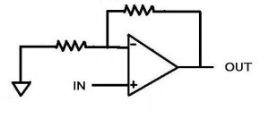
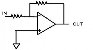
What if the signal coming from the sensor is too small though? What if we want to make it bigger? This is when we turn the op amp into an amplifier, using resistors. One of the more common ways of doing so is using the inverting input, shown below:

Figure 5: Inverting op-amp

Let’s go over what we know about this circuit. We know that the op amp wants both inputs to be the same. We also know that the non-inverting input is zero (because it’s connected to ground) and so the op amp will want the inverting input to be equal to zero (sometimes known as a “virtual ground”).  In fact, since the op amp has feedback through the top resistor (squiggly line if you didn’t know), then the (ideal) op amp will output just about any current and voltage in order to get the inverting input to be equal to zero.

So now our situation. A dashing young engineer hooks up a voltage source to the point “IN” set to 1 volt. This creates a voltage at the inverting input. “WHOA” says the op amp, and then it begins to output a voltage to make the inverting input point equal to zero. Since the input is 1 volt the op amp decides it better do the opposite in order to make the inverting input match the non-inverting input of zero. As fast as it can (infinitely fast for an ideal op amp), it outputs -1 volt. The inputs are both zero and everything is right in the op amp’s world. What about current though? We remember that current cannot flow into the op amp at the inverting input, so any current will be flowing through both resistors. If we have 1 volt at the input and a 1 ohm resistor at the input, then we will have 1 amp of current flowing (according to Ohm’s law V=IR). So when the op amp outputs -1 volt across the top resistor, there is a -1 amp going through it (assuming it is a 1 ohm resistor). The currents cancel each other out at the inverting input and the voltage then equals zero. The place where the currents meet is sometimes called the “summing node”. This is a useful representation when dealing with currents as opposed to voltages.

For the last part of this thought exercise, let’s look at a situation where the resistors at the input and at the top of the circuit are not the same. Similarly to above, the same dashing young engineer puts 1 volt at the “In” node. The resistor is still 1 ohm, so there is 1 A of current flowing through to the summing node. The op amp once again sees this 1 volt and once again says “WHOA, I’m unhappy about this” and starts outputting the highest voltage it can. However, in this situation, the top resistor is now 4 ohms. In order to create the -1 amp that is required to cancel the 1 amp going through the input resistor, the op amp must output -4 volts (remember V=IR).  We see that for an inverting op amp configuration, the ratio of the resistance of the top resistor to the bottom resistor determines the gain, or a multiplication factor from the input to the output. Also notice that the output is negative for a positive input, confirming that this is an inverting amplifier.

That’s the basics of it. Check back here for more about op amps, because there is a lot more to be said. Future posts might include other op amp configurations, design considerations and even the dreaded “REAL WORLD”, where the ideal op amp no longer exist.

[xyz_lbx_default_code]