Categories
Analog Electronics Learning

How an op amp works — Part 2

As promised, this post is a follow up post to explain the real-world behavior of an op amp. Here we will continue to anthropomorphize op amps in order to better understand their behavior and what they “want” to do. Also, we will look at some more complicated (but common) op amp configurations so that they are easily recognizable. Let’s begin.

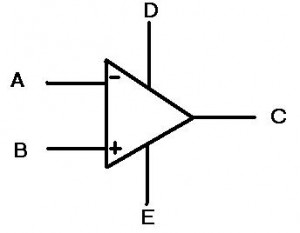
First, let’s look at the symbol for the op amp:

Whoa-ho! What the heck are those? Last time, there was only 3 lines coming out of the triangle and now there’s five! They’re multiplying!

Really the “D” and “E” inputs are the power inputs to the op amp. This means we are no longer simply dealing with the “ideal” case and are now going to look at the behavior with some realistic expectations. I know that when I was first learning about op amps, I was perplexed by this idea. I thought, “Well what is the point of putting power into an op amp? What do I get for it?” The idea is that as long as the signal at the input (or more accurately the difference between “A” and “B” is smaller than the power at the “D” and “E” terminals, then the op amp can amplify the signal. This gets very useful once you start encountering signals that change over time, or AC signals (as opposed to DC signals). Let’s look at this idea below:


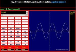
Special thanks to CoolMath.com for the graphing program!

On the top left, we see a SINE wave, which is one of the simplest time varying signals there is. Amplifying this signal would not shift the signal, but instead would make the entire range of the signal larger. If we used a 4x amplification, then we would get the top right picture with the larger signal. Notice in the bottom picture the overlay of these two signals. They do not SHIFT up, but instead look like they are stretched. The easiest way to think of all this is at the extremes. If in the first picture the highest point was 1 and we had 4x amplification, then the output would be 4. However, the middle point is 0 and that multiplied by 4 is still zero. Hence the reason the overlay shows the extreme highs and lows being “stretched” the most. Also, it is important to note that these are analog signals, so EVERY point in between the extremes is being amplified.

The power coming into the op amp also restricts how much the op amp can amplify a signal. Not only that, but sometimes you don’t even get to go to the limits! Say you have +15 volts attached to “D” and -15 volts attached to “E” (most op amps have lower voltages these days but +/- 15 volts still happens sometimes). Now let’s say you have a 1V signal coming into a non-inverting amplifier (shown below). The gain on this amplifier is set to 15 by making the top resistor 14 times less than the resistor connected to the ground (non-inverting amplifiers have a gain of 1+R(top)/R(gnd)). So our 1 volt signal is placed at the non-inverting input (the plus) and the op amp says “15 volts, coming right up!”. Ah, but the op amp doesn’t quite have it. The op amp outputs 13.4 volts are so and then stops. “But WAIT!” you say, “why can’t this op amp output as much as I wanted? The ideal ones can output INFINITY. Can’t I just get one of those?” The short answer: no, you can’t. Op amps have internal protection circuitry that limits how high the input to the op amp can be in order to protect it from blowing up. Additionally, the op amp must consume some of that power in order to actually amplify the input signal; this will be expounded upon in further posts (the internals of an opamp).

The final point in this continuing discussion about op amps, is known as slew rate. Really it is a discussion of how fast an op amp can go and is limited by capacitance. Inside of any op amp, there is a capacitor, or rather a bunch of components that act together as one capacitor. This creates a required charge time for the internals of the circuit (for a more advanced look at this topic, check out the allaboutcircuits.com article on capacitors and calculus). The end result is that the op amp has some limit to how fast it can “decide” what the output should be. If we think back to the signals above that alter with time, we can imagine a situation where they would vary so quickly that an op amp would not be able to keep up. The end result is that a circuit such as the non-inverting amplifier shown above has some frequency above which it can no longer accurately amplify. This is known as the bandwidth of the circuit and has implications in many audio, measurement and communication industries.

This post discussed some of the real world aspects of op amps. The next post will discuss the internals of the op amp, such as the transistor setups. Imperfections in the silicon and the realities of material science will show us that more of the “ideal” op amp model is not possible in every day life; some potential topics are the input bias currents, the voltage offsets across the input terminals and how they can affect everyday circuits.

[xyz_lbx_default_code]
Categories
Analog Electronics Learning Music

Replacing capacitors on my Wurlitzer 200A electric piano

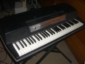
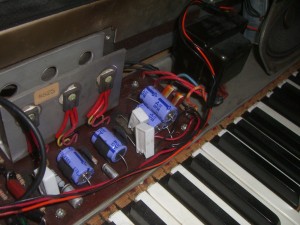
Things get old. Things eventually do not work anymore. Even the best engineers cannot design a system for part failures (unless they have triple redundant systems, like NASA). It is for this reason, I have decided to document on my blog the tune up of my Wurlitzer 200A electric piano (seen below) as opposed to the usual analog issues in the workplace today.

I mentioned this piano in my post about keeping it simple, namely not replacing EVERY component, only the ones that require an upgrade/replacement. It is a famous piano that can be heard in many types of music, spanning rock, soul, jazz and more.  Similar to the Fender Rhodes, the Wurly can be characterized by a darker, more over-driven sound and a built in vibrato (constructed from a simple oscillating circuit).

There are two components on these boards that need to be replaced the most often. The first is transistors, due to thermal stresses when they are over worked. In the case of my Wurly, the power transistors (seen below bolted to the large metal heat sink on the left) have started corroding, but have also had reduced output due to thermal stresses over the years. The board has upwards of 250 V and these transistors are ready to be replaced.

The other element that commonly needs to be replaced are the capacitors (the purple barrels seen above), specifically the electrolytic capacitors. An electrolytic capacitor is constructed by soaking paper in an electrolyte and sandwiching it between two aluminum plates (then attached to the leads of the capacitor). After about 10 years or so, the electrolyte begins to dry out and the capacitor degrades. Sometimes this can lead to a catastrophic breakdown (think “POP” or “BOOM”) or it can just mean that no signals will get through. Whereas I think of capacitors being frequency-dependent resistors (where the lower the frequency, the higher the resistance), these capacitors instead have resistance at ALL frequencies, due to the fact that the dielectric constant has gone from that of electrolyte to that of air. The final effect of all of this is a poorer sound, especially at the higher frequencies that are supposed to “pass through” a capacitor.

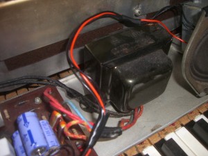
I am also hoping this will take care of some of the “hum” sound (most likely from 60 Hz); I’m hoping this will be resolved once the power filtering capacitors are replaced. I think that the ripple current may be higher since the capacitors have slowly degraded. This will impose the 60 Hz from the wall power onto the signal coming from the vibrating reeds (through the capacitive pickup). I also am wondering if the transformer (below) requires replacement, but I think I will replace the capacitors and transistors first.

That’s all for now, I will update more as I actually replace these capacitors. For now, enjoy the pictures and the sound samples (above links to Last.fm).

Categories
Analog Electronics Learning

How does an op amp work? How do I use an op amp? — Part 1

How does an op amp work? How do I use an op amp

These are questions that I have asked at two periods in my life. The first time was in my introductory circuits class and around that time I really didn’t care (beer was a priority). The second time was when I dove headfirst back into analog electronics for my new job and had to re-teach myself a lot of things. I really appreciate the opportunity I had to re-learn everything because the second time around, I think I got it right.

OK, so let’s start simple. What is an op amp? Whoa, loaded question. For our purposes here (and just for now), let’s say it’s just a symbol.

Figure 1: Just a symbol folks, nothing to see here

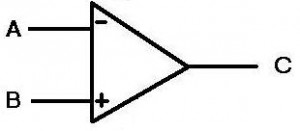
To keep things basic, the A & B points are the input, the C point is the output.This symbol is an IDEAL op-amp, meaning it is impossible to construct one and really the expectations for the op amp are unrealistic. But this is the internet and we can do what we want on the internet, so we’ll just use the IDEAL op-amp for now.

Figure 2: Inverting Ideal Op-amp

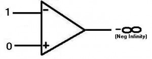
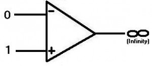
OK, so now you know what the symbol is, but what does it mean? Well, the idea is you put two electrical signals into the inputs then the output changes accordingly. It takes the difference between the inputs and amplifies it, hence operational amplifier, or op amp. You may have noticed that input A has a minus symbol and input B has a plus symbol. So let’s say that the input to the minus, or INVERTING, input is 1 (for simplicity’s sake…this site is about analog so that value could be ANYWHERE from 0 to 1 or higher! Just thought I’d mention that). The input to the plus, or NON-INVERTING, input is 0. Now the op-amp is in an unbalanced state. The device is designed so that when this happens, the output goes as negative as it can. For the ideal case, we say this is negative infinity, but that’s not really possible. More on that later.

Figure 3: Non-inverting Ideal Op-amp

Conversely, in figure 3, if we put a one on the non-inverting and a zero on the inverting input, the op amp output would go high, infinity for our purposes here. The important thing to know is this:

The op-amp always “wants” both inputs (inverting and non-inverting) to be the same value. If they are not, the same value, the op amp output will go positive or negative, depending on which input is higher than the other.
(Throughout this article I will continue to anthropomorphize op amps…best to get used to it now)

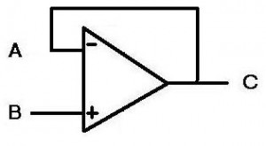
Alright, so how do we use this in circuits? If we wanted to find out if two signals were different, we could tie the signals to the inputs of the op amp, but then the output would go to infinity. This would not do us any good. The answer to this and many other questions in the universe is feedback. We are going to take the output and tie it back to the inverting input. Now the circuit looks like this:

Figure 4: A buffer
Figure 4: A buffer

First, we assume that the circuit has all points start at zero (point A being the most important). Next, we put a value of 1 (like the picture in figure 2) at the “B” non-inverting input. “WHOA,” says the op amp, “THIS AIN’T RIGHT!” So now the op amp puts its output to as high as it can, as fast as it can. This feeds back from the output (“C”) to the inverting input (“A”). So as the output moves closer to 1, the op amp is happier and backs off the output. When the input at A is the same as at B, the op amp is happy and stays there (but maintains the output of 1). The key here is that the op amp moves as fast as possible to get both inputs to be the same.

Why would someone use a buffer? Well that brings us to the next point about op amps, specifically ideal op amps:

Ideal op amps have infinite impedance (resistance) at their inputs. This means that no current will flow into the op amp.

A common use for a buffer is to supply current to another stage of a design, where the buffer acts as a gateway. So when the buffer “sees” a voltage at the input (“B”), it will output the voltage at “C”, but will also drive that voltage with current (as much as you want for an ideal op amp). This would be useful if you have a weak signal at the input, but want to let some other part of a circuit know about it. Perhaps you have a small sensor that is outputting a small voltage, but then you want to send the voltage over a long wire. The resistance in the wire will probably consume any current the sensor is outputting, so if you put that signal through a buffer, the buffer will supply the necessary current to get the signal to its destination (the other end of the wire).

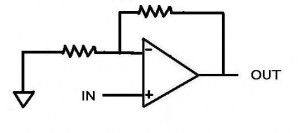
What if the signal coming from the sensor is too small though? What if we want to make it bigger? This is when we turn the op amp into an amplifier, using resistors. One of the more common ways of doing so is using the inverting input, shown below:

Figure 5: Inverting op-amp

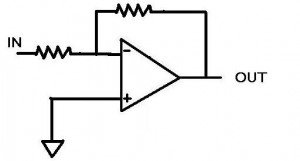
Let’s go over what we know about this circuit. We know that the op amp wants both inputs to be the same. We also know that the non-inverting input is zero (because it’s connected to ground) and so the op amp will want the inverting input to be equal to zero (sometimes known as a “virtual ground”).  In fact, since the op amp has feedback through the top resistor (squiggly line if you didn’t know), then the (ideal) op amp will output just about any current and voltage in order to get the inverting input to be equal to zero.

So now our situation. A dashing young engineer hooks up a voltage source to the point “IN” set to 1 volt. This creates a voltage at the inverting input. “WHOA” says the op amp, and then it begins to output a voltage to make the inverting input point equal to zero. Since the input is 1 volt the op amp decides it better do the opposite in order to make the inverting input match the non-inverting input of zero. As fast as it can (infinitely fast for an ideal op amp), it outputs -1 volt. The inputs are both zero and everything is right in the op amp’s world. What about current though? We remember that current cannot flow into the op amp at the inverting input, so any current will be flowing through both resistors. If we have 1 volt at the input and a 1 ohm resistor at the input, then we will have 1 amp of current flowing (according to Ohm’s law V=IR). So when the op amp outputs -1 volt across the top resistor, there is a -1 amp going through it (assuming it is a 1 ohm resistor). The currents cancel each other out at the inverting input and the voltage then equals zero. The place where the currents meet is sometimes called the “summing node”. This is a useful representation when dealing with currents as opposed to voltages.

For the last part of this thought exercise, let’s look at a situation where the resistors at the input and at the top of the circuit are not the same. Similarly to above, the same dashing young engineer puts 1 volt at the “In” node. The resistor is still 1 ohm, so there is 1 A of current flowing through to the summing node. The op amp once again sees this 1 volt and once again says “WHOA, I’m unhappy about this” and starts outputting the highest voltage it can. However, in this situation, the top resistor is now 4 ohms. In order to create the -1 amp that is required to cancel the 1 amp going through the input resistor, the op amp must output -4 volts (remember V=IR).  We see that for an inverting op amp configuration, the ratio of the resistance of the top resistor to the bottom resistor determines the gain, or a multiplication factor from the input to the output. Also notice that the output is negative for a positive input, confirming that this is an inverting amplifier.

That’s the basics of it. Check back here for more about op amps, because there is a lot more to be said. Future posts might include other op amp configurations, design considerations and even the dreaded “REAL WORLD”, where the ideal op amp no longer exist.

[xyz_lbx_default_code]

Categories
Analog Electronics Music Renewable Energy Supply Chain

Keep it simple, stupid

Keep it simple, stupid

The KISS principle is pertinent in nearly every aspect of my life. I can’t begin to relay the number of times I have had to convince myself to step back from a situation–engineering or otherwise–and ask what the simplest solution is. Be it electronics at work or at home, renewable energy or even my investing, I encounter the KISS principle over and over again.

A tenet of the ever-expanding chip market is that the more functions that were once done with discrete components and can now be moved into the confines of a chip, the better. This is done either directly on silicon or by setting multiple pieces of silicon next to each other in the plastic packaging and wiring them together. This idea started a long time ago but is being to manifests itself in many different ways. One of the earliest examples is the op-amp. True, the form and function of the op-amp is different than the cascodes and the vacuum tubes that preceded it; but the idea of bringing the capacitor (to control the slew rate) and the transistors required to drive the differential inputs and the output all into the same package were just the first examples of combining discrete elements into an easily re-usable device was new. Another driving force was the idea that this device can be mass produced and sold at a lower cost thanks to economies of scale. More recently we have seen more and more functions brought into the chip packaging. One such example is the FPGA, which not only reduces the need for external logic gates in some bulky package, but it also makes it reconfigurable. And now, predictably enough, this same concept is being brought into play with analog! There are now chip manufacturers that make Field Programmable Analog Arrays (FPAA). Usually this consists of an op-amp, some analog switches and passive components, such as resistors and capacitors (for filtering). The device can be “programmed” to select any number of functions, with the potential for ever increasing complexity (though signal integrity would be a concern of mine). The final example is a product offering called the uModule from Linear Technology, with others doing similar things. It is an interesting concept because they are bringing in even more discrete components, such as inductors on a DC-DC converter; inductors are typically set outside the chip because of size concerns.

So how do these complicated chips affect designers and end users? They make things simpler (in theory). Open any modern day cell phone or look at a tear down, and you will see very little on the board in terms of discrete components (granted, this is also for space concerns). But chips that have everything included really do make everything simpler. Sometimes they are drop in solutions, such as with the uModule. All you need to do is determine the DC to DC conversion you want and then populate the board with their chip and two capacitors. On cell phones, there is usually 1 chip for each type of communication protocol (WiFi, CDMA, etc). If and when FPAAs ever become popular, they will only require that you populate a board with them, route the proper signals and then program what kind of filtering and amplification you want. This could even be as simple as saying what knee frequency you require and if you are particularly sensitive to ripple in the passband or stopband. Then the chip would know to use a butterworth, chebyshev, bessel, etc to get your desired results. The main point is, more and more people will be able to design systems, because the chip makers are paying attention to the minutiae (for a price, of course). This then allows fewer designers to make more designs, faster. Companies love the sound of that, because then they get more bang for their buck. As an aspiring futurist, I would even venture a guess that the system designers of tomorrow will really be software people with a knack for picking out parts. They will know what they need each part of the design to do and then will go through a catalog that will do it.

OK, so aside from using systems on a chip and not bothering to design systems when I can buy them, how else do I keep it simple? Well, a burgeoning hobby of mine is vintage analog electronics. Really I bought a 1968 Wurlitzer 200A electric piano on a whim and decided to fix it up/learn how to play it. The latter of those two goals is too lofty in the near term and shan’t be discussed here; however, the former of those goals has presented some good lessons from pulling this fine piece of equipment apart. When I first opened it and saw the components, I decided right away that I would  be redesigning everything, including a new circuit board and using the most efficient new parts. However, as I’ve dug into the design I’ve found that not only would this be silly, it could be detrimental. One of the best things about vintage audio electronics is the intangible “warm” sound they often have. This could be from using vacuum tubes or just noisy components that were designed to create the best sound they could at the time. If I replaced everything, I would lose the natural sound of the instrument, basically rendering it useless (in terms of re-sale and in terms of playability). Instead, the simplest course of action is to replace the dried out capacitors with the closest match I can and leaving everything else alone. Simplicity wins again!

Renewable energy, specifically solar, has begun taking the KISS principle to a new level. Solar panels are not yet cheap or abundant as we want and need them to be. But mirrors are! So why not take a really simple method of essentially putting mirrors on a parabolic dish and then pointing it at a water tower? This simple approach then forces the steam through a turbine and voila, electricity. Now create a project that does this many times over, in a desert no less, and you have a serious contender for long term energy independence.

“The best way to own common stocks is through an index fund.”–Warren Buffett…The best investor in the world and one of my personal heroes, says this about 99% of investors. Regardless of what this says about his confidence in the average (and not so average) investor, I think it is a perfect example of keeping it simple. In fact, it doesn’t really get much simpler. And history has proven it too. In 2006, a study found that only .6% of active money managers can beat the market. Keeping it simple and buying that index mutual fund will ease your mind and your wallet!

Do I follow these ideas in my life and work? Sometimes. But as I experience more and more, I find that the KISS principle is one that could bring more harmony into many different aspects of my life.

Categories
Analog Electronics Learning Work

My name is Chris…and I’m an analog engineer

Or am I?

I read technical publications on a pretty regular basis. And more and more lately, especially with the lull in the economy, I read about how jobs are going offshore or overseas. Sure, this concerns me, I’m human! Plus, I’ve inherited a worrisome nature from my mother. But I’ve had the fortune of reading a lot of articles about how analog engineers are in short supply. Even how they’re moving into green technologies!

Yahoo!” I think.

But wait a second, what’s all this.

I have read how analog engineers are hard to find. I know that the experience is both rare and valuable. But what kind of analog engineer I ask? Most of the articles I see are regarding silicon design and regardless of what I have done in the past with Samsung, I have never had the opportunity to look at analog design on silicon. And I have to wonder, am I allowed to call myself an analog engineer? I’m going to go with yes.

Here’s why:

  1. I know how to use an op amp
    • That’s one of those triangle things, right? I use these all the time and they are the basis of any analog engineer’s work. I feel like the main difference between myself and an engineer designing in silicon is I go out and buy a part for a dollar, they just go into a CAD library and plop one down in their design (and maybe mess around with it to get the specs they need). Anyone out there know if this is true or not?
  2. Yes, I even know how a transistor works
    • Granted, my silicon level knowledge is a little weak (I never liked calculating the number of electrons flowing through a PN junction…it just seemed so anti-Heisenburg). But plop an NPN transistor down in front of me (or a symbol of one), and I think I can fare pretty well. A great test of basic knowledge is in the chapter “A New Graduate’s Guide to the Analog Interview”. See how many of this limited passage you can get right.
  3. I know how to put it all together
    • There is a lot more to analog electrical engineering than knowing equations. A good example in my specific branch would be talking to vendors and getting pricing on parts. There are some big swings that can occur on prices of parts! Another example of putting it all together includes other aspects of design you might not think about. How about supporting a product 10 years down the line? I haven’t done this one personally (given my relatively short career thus far), but I’ve had to help out with some designs where the original designers were no longer around. And I’ll tell ya, some of those components were not meant to last! Needless to say, there is a lot of other tasks out there than just thinking up a circuit.

So even though I don’t intend on changing what I call myself anytime soon, I will clarify my skills. I am an analog system designer. Is that too far off? No, I don’t think so. Even the limited amount of design I’ve done really fits into that category. I have strung together a lot of components in order to create systems capable of processing analog signals. Further, sometimes the available system components (op-amps, buck/boost converters, etc) need to be made with passive components because of individual system constraints (meaning the stuff that vendors offer just don’t do what we need them to). I think more and more though, the industry will go towards system designers, simply because of rising costs. As systems get more and more complex, economies of scale mandate that people specialize in order to win business. We have also seen trends where chip makers are beginning to reach practical limits of how much better they can make certain devices (op amps, for instance). As such, we’ll see that the chip makers put more and more functions inside of chips.

So maybe one day I will work for a chip maker, trying to shove more components into a package? I enjoy the thought of creating a component that thousands if not millions would use. Perhaps this will be all that will be left to do? I’d obviously like to start learning it all before it’s the last frontier of design. Perhaps one day our tiny cell phones and other gadgetry will be nothing more than a screen and a single chip with every required function in it. But if I’m not making the screen or the chip, hopefully they’ll still need someone like me to hook that chip up to that screen. Who knows what the future will hold?

One final (and mostly unrelated) note I’ve been meaning to put in a post; writing about analog issues seems to be as good a time as any.  I’m sure at least one or two people noticed (probably not), I changed the tag line on my blog from “Chris Gammell’s Renewable Life” to “Chris Gammell’s Analog Life“. A few reasons: I think it makes more sense (I’m not Hindu, so I don’t really think life is “renewable” per se); the world around us is truly analog (as much as marketers would have us believe that music is “digital”); and to be blunt, I like the sound of it better.  Plus, I doubt too many people will be like “Wait, where is my favorite site??? Ohhhh, it just changed names…”.  This doesn’t mean I will stop looking at issues facing renewable energy, just that I want the focus of my site to be on analog.

That’s all for now. Chris Gammell, analog electrical engineer, out.

Categories
Blogging Learning Life Supply Chain

Alltop

Welcome Alltop visitors!

I am unfortunately becoming an information junky. I have friends in DC and they have mentioned on multiple occasions that this is the norm at least in our nation’s capital; that people consider being news-knowledgeable to be a social status. Well, I guess I’m part of it; I love being connected and being in the know, especially about engineering and analog electronics. Don’t worry though, I’m still pretty low on the social ladder and I like it that way :).

Alltop.com is a news aggregator community and I am now a part of that community. I found out about it from a badge on Penelope Trunk’s blog (my favorite for career related issues) and I requested to be a part of the community (yes, I’m that guy). It was started by Will Mayall, Kathryn Henkens, and Guy Kawasaki. (EDIT: I had confused Guy Kawasaki and Robert Kiyosaki. Sorry!) As far as I have read, all are serial entrepreneurs and Alltop is a great start.

Anyway, if you are interested in finding a lot of information in one space, this is it. I kind of think of it as a Google Reader, but someone else is filing all the stories into neat little compartments. You’ll find my site under “E” for engineering, but I’m thinking about lobbying them to file me under “N” for nerd. We’ll see. Enjoy Alltop!

PS. Fun fact about Alltop.com…the “Moms” feed has the most of any, so they have to limit the story listing. Who knew there were so many Moms out there blogging and writing? (well, Moms apparently…and Alltop.com)

Categories
Analog Electronics Learning

Great resources for learning about analog electronics

I am absolutely floored by the internet every single day. I often wonder to myself if given the proper linking, guidance and mentoring, whether schools are even necessary any more (maybe the different methods are exactly what we need). This would of course also require some strong drive to learn and a whole lot of time on your hands, not to mention eyes that can bear reading computers screens all day. But I think it is possible; Some schools have even offered up their entire course catalogs online.

Me? I’m an information glutton. I will get 10 books from the library just because I get so excited about them, even if I only have time to read 2. As such, I thought I would clue everyone in to the absolute wealth of information on analog technology on the web. Most of the information you are going to find will be in the form of application notes (basically a cookbook on how to use a particular circuit). But sometimes you will find actual courses and training. I’ll be sure to list these first.  If you know of any other great resources, please leave them in the comments section! Enjoy!

National Semiconductor – The Analog University. Forget saving the best for last, this is by far the best resource I have found to date. There are full length courses that would make MIT blush.

Texas Instruments – This site has information on the entire spectrum of design from learning a concept, picking parts, creating the design and then simulating it.

Linear Technology (link 2) – These are app and design notes from one of the more robust companies out there.  There are also some great articles, some by none other than the great Jim Williams. See other work by Jim here.

Analog Devices (link 2) (link 3) – Analog devices is a monster supplier and has a lot of resources at their disposal. This allows for some great learning content. The links listed include the AnalogDialogue, a nice forum for analog discussion.

Here are some others with mostly app notes, but don’t discount them:

Maxim Semiconductor

ON Semi

Silicon Labs

NXP Semiconductor (formerly Philips Semiconductor)

That’s all I have for now in terms of online resources. I think I’ve maybe gone through about 2% of everything available, so I’ve got some reading to do!

On a side note, I’d like to welcome readers from the Motley Fool! Thanks for coming and feel free to take a look around!

Categories
Analog Electronics Life Renewable Energy

Inventions for the future

I was talking to my friend the other day about ways to become rich and famous. Surprisingly, blogging was not on the list :-). The best I could come up with for an engineer like me was to invent something and sell it. Even better, invent one thing, manufacture it, use the profits to invent something else, and so on.

Then I started thinking about it and the thoughts of money and fame kind of melted away. Sure, that’d be nice, but what does the world really need invented? What could change the world? What could start the next revolution (i.e. industrial, technological, etc)? Where is the future taking us and most importantly where are WE taking the future?

  1. A new method of propulsion for air travel
    • There is no doubt that the world is dependent on fossil fuels. And for all the talk of renewable energy and even all the progress of it, there are still some things that will be dependent on fuel. In 2004 alone 7.2% of the oil consumption came from air travel/military airplanes. That same link also mentions that there are some other ideas in the work for using hydrogen, but that is a ways off (and still has a significant environmental impact). I have also seen biofuel options, and even the government is in on the idea. Unfortunately, oil and biofuel are the most energy dense option option. Until we have significant advances in energy technologies, using fuel cells or batteries will not be possible. Perhaps renewable energy for travel is not viable by air at all? Maybe electric trains or boats will be the most efficient way, but these things need to be discovered. Of course, there have already been some…um…interesting ideas.
  2. A new method for energy storage
    • There’s a lot of chatter about this lately (see above). Batteries just don’t seem to be doing the job they need to, so people are looking to other options. In fact, the doozy of an article I reference happens to be on this very subject (hint: it’s not a positive article).
    • We need to develop high efficiency, low cost storage devices because renewable energy (solar, wind, geothermal, cow farts, etc) do us no good unless we can transport that power. We could try to make hydrogen, but that’s not exactly the safest way to transport energy. Long term, I think electricity is our best bet in terms of delivering power to devices, even if that’s not the safest option either (I’m not so sure there will be one). Some might say I’m a little biased on the whole idea of electricity though. To electricity’s benefit, a lot of the infrastructure is in place, as are the devices (i.e. electric motors).
  3. A new method for space travel
    • OK, maybe I’ve watched Star Trek and Star Wars once or twice in my life. But just because I have seen that and dreamed about it doesn’t mean it’s not a good idea. Long term, the earth isn’t going to cut it for us. Either some wacko will finally set off a bunch of nukes, we won’t figure out a solution to global warming, we’ll run out of non-oil natural resources or medical technology will extend life to the point where population is unreasonable. So we’ll have to get out there and poke around, find a new hang out. It’s not exactly a short bike ride, either: The closest star system is Alpha Centuri, a short 4.22 light years away. What we need is some way to either approach the speed of light or find another way around (wormholes, improbability drives, etc). The point remains, the whole take a bunch of rocket feul and shove it out the back of a space ship just isn’t cutting it anymore. I like the idea of ion engines, but we need to see some more progress.
  4. A universal translator
    • Every time I think about world events, I think how lucky I am that I speak English. There’s no other language in the world that people are more eager to learn. I mean, I worked at an international company for 2 years and only learned 4 words in their native language! (hello, thank you, beer, please) That includes spending 8 weeks in Korea bumbling around hoping others would speak English (they did).
    • Imagine it though. Imagine if there was a way that all people could instantly communicate at least on a low level (aside from hand gestures). It would open new pathways to business, travel and most importantly international relations (especially tense ones). I had heard rumors that there were some people working on such a device, but could not find any further information on it. If this ever became commercially viable, it would change the world…and then Rosetta Stone would get very angry.
  5. Memory/Cognitive enhancers
    • This could come in one of two forms. The first would be a drug/supplement induced type, where we take what the human mind has to offer and then improve it by offering more resources (oxygen, nutrients, etc) or whereby we stimulate  the memory center to work harder or faster (think caffeine, but healthier, hopefully). The other method would be more radical, but I could see becoming a viable option in the future. That would be neural implants (think matrix) whereby our brains interact with computers/electronics. There are tons and tons of ethics questions surrounding such a device, but it will be possible someday. I envision this kind of device allowing ease of access to information and even better access to communication between people hooked to such as system. Who needs a universal translator when you speak binary?

Sure, there’s other stuff that would be great to invent or even just see invented. Even better, there’s some really silly ideas out there that are fun to laugh about. I think it’s important to dream about these kinds of things though. For those interested, I would highly suggest that you look into the work of futurists such as Ray Kurzweil or inventor Dean Kamen. Both of these guys have driven some amazing inventions and will continue to do so. Plus Kurzweil has been pretty accurate on his predictions before, so trying to fulfill some of his predictions probably isn’t a bad idea if you want to invent something. I’ll let you know when I’ve come up with something.

Categories
Analog Electronics Life Work

Analog Definition

I have been working on a doozy of a blog post for about a week now. It’s almost there and I will definitely release it this week. However, in the interim I have been thinking about my blog and my (analog) life and realize I’ve never really defined it for many people. And like some others, I get questions about it:

What is Analog? What is my definition of Analog?

Analog is everywhere. Analog is the opposite of digital. It is continuous. It is real. Analog are the sights we see and the sounds we hear. Analog is the beauty of a symphony and the complexity of a transistor.

OK, maybe that last part is a little out there. But let’s get down to it. When I say that I am an analog engineer, what does that mean? It means that I work on devices that are primarily in the analog realm. As an example: If I made an electronic circuit that counted to five, there would be many different ways to do it. However, I think there are two basic definitions when it comes to circuits. I could create a circuit that counts 1, 2, 3, 4, 5. This would be a digital circuit, because there are only 5 values, and they are not continuous. However, an analog circuit would count something more like 1.00000, 1.00001, 1.00002, 1.00003… 4.99999, 5.00000. There would technically be an infinite amount of information in between 1 and 5, and the precision would be infinitely more that what I have shown. However, as humans, we decide to define numbers to explain the world in finite amounts, either because of time constraints (it would take a very long time to count otherwise) or because of simplicity (we all learn to count to ten because most of us have ten fingers).

Alright, so that’s a good start. Analog = continuous, digital = not continuous.

So why did I choose analog? Well to be completely honest, I didn’t. I got lucky and was presented with an opportunity to work on analog. It seemed to fit many of my goals and it was a welcome change of scenery, not to mention that analog engineers are pretty scarce (and therefore being one has inherent value). However, the best part is that every day I discover something new about it. The weirdest thing I find though, is that I am working on problems that have been around for 50 years. There are people working on the newest digital devices at the bleeding edge of technology, but that stuff doesn’t really interest me. I like the problems that have been around because there need to be more succinct and elegant solutions. Plus, I think the most interesting stuff actually happens when you take all that digital information in the form of 1’s and 0’s and try and put it back into analog. Or vice versa, getting analog signals into digital form isn’t easy either.

Ok, one last example then I’m done. Here’s a decent way to think about what I do. Say you have an iPod. You hit the play button to turn on your favorite track. What happens? Well to start with, all the digital electronics pulls the data off of the flash memory. Then it says: “OK, I have 1’s and 0’s, now what?”. It pushes these 1’s and 0’s into a digital to analog converter (DAC). Now it’s a tiny little sound wave (but an analog signal, yay!). Ok, so now the iPod says “What volume did they want?”. So it takes the volume you select and it amplifies the signal so it will come out of your headphones at the proper volume (not too loud, kids) and you can walk down the street boppin and groovin. Everything from the DAC forward, is similar to what I work on (I don’t do audio, but the ideas are the same).

So there’s my analog definition. I hope it helps and I will reference and revise this post as my career and life change. Cheers!

Categories
Analog Electronics Life Work

Should I get a PE license?

I’ve never thought of myself as particularly upwards mobile in my career (yet). I’m actually very happy where I am right now, learning as much as I can and progressing through the rigorous on the job learning and tribulations I’ve been experiencing so far. However, the sign of a good career path is one where you are surrounded by people who both push you and are good role models for you. I am lucky to be in such a situation and as such, am thinking about getting my Professional Engineer (PE) certification.

This is actually not as common for electrical engineers as it is for other engineering disciplines. For example, most civil engineers can’t touch anything until they have obtained their certification. With the recent bridge disaster in Minneapolis, I can’t say I really object to this. However, just today I was talking with 2 of the 4 PEs at my company, both of whom happen to be in my group, and both were very convincing on reasons why it’d be good for a young engineer to take the Fundamentals of Engineering (or FE, the qualifying exam).

  1. Use it or lose it
    • Even the sites about the FE exam say it: The sooner you take the exam after school, the higher likelihood of passing it. It makes sense. You’re closer to your exam-taking, all-night-cramming, super-stressed-out days of engineering school. Once you enter the practically driven world of the workplace (as opposed to “academically driven”, to put it nicely), you lose some of those skills and they are hard to get back.
  2. Self-employment
    • Aside from the bridge builders and the others who need a PE to sign off on stuff, working as a consultant or a contractor sometimes requires that you have a PE (as an electrical engineer). As I’ve written before, self-employment is an eventual goal of mine, so that’s another reason to consider this.
    • Many power companies actually require that their engineers have their PE. This is because they work “directly for the people” and because the engineers sometimes actually work as contractors for the power company. Oh, and the stuff they make can really kill people quickly, forgot about that.
  3. Feather in the hat
    • As one of the two engineers I was talking to put it, “If you have 100 electrical engineers in a room and ask who has a PE, maybe two will step forward”. Great point. This is a way to show that you’re capable of achieving AND that you’re willing to stand behind your designs. As I really love reading about (and how this blog kind of came to be), careers these days are all about branding and a PE just helps strengthen your brand.

I could tell myself I’d wait until after grad school, but let’s be honest: grad school is about graduating and getting the paper. I think any time I take this exam, I would need to study pretty far in advance. So why not now?