Categories
Analog Electronics Economics Politics Renewable Energy

Sustainable Cleveland 2019

I will be attending Sustainable Cleveland 2019 later this week. It has given me a renewed interest in renewable energy and has really been great motivation to learn more about my city.

The summit will be a gathering of more that 600 people from different walks of life in Cleveland, all trying to figure out what we need to do in order to become a leader in various fields of sustainability. The 2019 part of the title refers to the Cleveland 30 year from now, when all of the areas of sustainability will hopefully have been achieved. These sustainability initiatives could include:

  • Renewable energy production
  • Advanced energy (infrastructure)
  • Advance material fabrication and advanced manufacturing operations
  • Sustainable, local food sources
  • Green buildings (LEED certifications)
  • Stringent environmental policies, especially to protect our water source, Lake Erie
  • Sustainable Business Practices

So what can we do as a group of non-policy makers to actually drive any change in this city? A question I’m not completely sure of the answer. At the most basic level, I think this summit will give the citizens and drivers of change in the city a chance to tell the administration what they think. In fact, the entire summit is being hosted by the mayor, Frank Jackson, so I am guessing that’s exactly what he’s looking for. Beyond the basics, there is a methodology being implemented known as Appreciative Inquiry; I’m not into organizational behavior, but from what I’ve read it’s a popular method. The leading researcher in this field, David Cooperrider, will also be present at the summit to lead and guide us. I was surprised to later learn that Dr. Cooperrider is a sitting professor at my alma mater, Case Western Reserve University. From what I have learned about the method so far (which in all honesty seems a bit touchy-feely to me), it is about bringing people together while they are still excited about a prospective idea, instead of after problems have developed and that same group is only trying to fix the problem. It has proven successful for many groups thus far so I am eager to learn more about it.

Although this was the first time they decided to host such a summit, the organizers required an application for entry, to ensure people who were signing up were serious about their pledge to attend (the summit requires a 3 day commitment). I thought including some excerpts of my application would help illustrate why I think attending a summit like this is important (Warning: I was very interested in attending, so I felt it necessary to toot my own horn a bit. You’ve been warned) :

Describe what draws you to this summit.

I understand that a 10 year plan is only as good as the people that are writing and later following it. I want to be an integral part of the planning progress so I can help shape a future city that is sustainable and one that I can continue to be proud of. I am interested in meeting others that are passionate about moving Cleveland  towards a future that is sustainable, successful and forward-looking. The people at this summit will be the leaders of the next phase of Cleveland’s evolution and I would like to start working with them as soon as possible.

What unique aspects will you bring to the summit (education, life experience, etc.)?

I currently write a blog that discusses electrical engineering and renewable energy. I write on topics relating to my profession (analog electrical engineering), my generation (Gen Y) and I tie it into content about emerging renewable technologies. I also have a unique perspective, being a student that left the area for a job after college, thereby contributing to the “brain drain” that has affected much of Cleveland; I have since been one of the few that has returned (in 2008) so that I could help contribute to the city and pursue my passion at a company that is a leader in the measurement industry. My work at Keithley Instruments has given me insight into the needs of renewable energy producers and allowed me to work with some of the finest engineering minds in Cleveland.

I feel that I bring a fresh perspective on the technological aspect of building a sustainable Cleveland. As someone who works in an industry that serves renewable energy and as someone who aspires to work more directly in the renewable energy sector, I feel that I can help define where Cleveland will be able to best capitalize on new technologies and strong business opportunities. These will drive the future growth of Cleveland as both an economic hub and as a model for hosting sustainable and eco-conscious companies.

What do you think are Cleveland’s biggest strengths or best assets?

I believe that the students graduating from local Universities will be the foundation upon which the next phase of Cleveland will be built. Enticing them to stay in Cleveland and encouraging them to create new companies will generate revenue and jobs in Cleveland. The technology and companies that are created will drive local development and help bring in more residents and investment. Furthermore, I believe the Universities that are producing these students are an asset and that they should be assisted in post-graduate retention and building businesses out of commercialized research efforts.

A second more obvious but yet untapped resource is Lake Erie. In terms of energy, I believe Lake Erie can produce a great deal of clean and sustainable power for residents in Cleveland and surrounding areas. From a sustainability perspective, the availability of fresh water must be considered and protected, as this will become an increasingly scarce resource as the world warms. Additionally, the wildlife and food sources the lake provides must be taken into consideration when planning for a more sustainable city and region.

What do you envision for Cleveland in the year 2019?

I envision a vibrant job market based on renewable energy companies that have sprung up over the past 10 years. More importantly, I see educational and research hotbeds such as Case Western Reserve being used as a launch point for multiple new industries and technologies. I see renewable energies being harvested from Lake Erie in the form of wind turbines and wave harvesting. I see axillary industries such as test & measurements adding even more to local economies and highlighting what Cleveland has to offer the world. I see tight-knit communities encouraging conservation and recycling and teaching these concepts in schools. I see programs in place to help every city have affordable recycling. I imagine local and regional governments encouraging restructuring and consolidating existing infrastructure as opposed to creating new sprawl. I see those same governments encouraging outside investment in the newly reconstructed and consolidated areas and in the new companies that have helped revitalize it . And hopefully, I see my own renewable energy company creating products that change the way we consume energy or how we cleanly produce it for use in energy efficient devices.

I feel that if nothing else, I will get the opportunity to meet others interested in sustainability and renewable energy in Cleveland. That alone could provide a great foundation for forming companies and coalitions later to help advance the city towards a sustainable future. On the other hand, I am hopeful that our work using Appreciative Inquiry will help lay a groundwork for where the city needs to go and what we need to do as a community to achieve our goals. I know there will be many planned follow up activities and I plan on discussing them more on here later. I would hope that my albeit limited audience might help to publicize the actions the city will take in the future.

Are you attending the Sustainable Cleveland 2019 summit? If you are, please let me know! If not but you have ideas that you think I should try to talk about while I am there, please let me know in the comments. I am interested to share what ideas I already have and if I can bring more voices than my own to the summit, I think it could be beneficial for everyone.

http://en.wikipedia.org/wiki/Lake_Erie
Categories
Analog Electronics Renewable Energy

What the heck is a Smart Grid? (Part 1)

First off, a smart grid does not yet exist. It’s not exactly dumb, but it’s unwieldy and needs some help getting itself under control.

So let’s think of the electricity grid as an elephant.

It’s big, it’s powerful and it takes a ton of work to get it moving in one direction or another. It’s also really expensive to get it from one place to another. If you want to move an elephant over a distance of hundreds of miles, it’s going to want some peanuts, after all.

A Smart Grid in this analogy is the trainer that controls the elephant.  The consumer is a person off in the distance, holding a peanut. And elephants love peanuts, so they will naturally go where they are. The trainer might be able to guide the elephant towards the people willing to pay the most peanuts. The trainer might also be able to tell the consumer to save their peanuts because getting the elephant at certain times of days will be expensive. And for the health of the elephant, he can say “enough is enough” and start to scale back how many peanuts the elephant is really allowed to eat that day. In the end though, the trainer is only guiding the elephant. The things that truly are controlling the elephant are how much energy he has and how many peanuts people are willing to offer him.

So how does an elephant relate back to the actual power grid? Well, think of a typical coal power plant. The coal is used to heat water, the water turns to steam, the steam turns a turbine and then the water is cooled and recycled to be used for another cycle. The AC power is distributed to transformers that step up the voltage of the signal to thousands of volts before the power is pushed through transmission lines. When you flip a switch in your house, you allow current to flow into whatever device is “requesting” power, thereby utilizing some small portion of the total energy on the grid. Now, if there were 10,000 people trying to turn on their clothes dryers simultaneously, the system will likely not be able to keep up. More power stations could come online, but the instantaneous need would instead likely cause blackouts and brownouts to occur, leaving customers without power. So what they do is try to curb everyone turning on their clothes dryer at the same point every day by charging a lot of money for using the power then. They say, “Why not run the dryer at night? We’ll make it worth your while!”. The Smart Grid/Trainer is there to try and balance the needs of the consumer and the ability of the power generators. It will hopefully save people money and allow power generation facilities to avoid turning to readily available energy (coal, natural gas) to fulfill the demand.

A smart grid has a potential to bring a lot of engineering jobs, especially in waning job markets such as the US. I plan to write more about the Smart Grid because I truly believe it will bring some innovation and employment to whoever jumps on the technology first. There are a lot of pieces to the eventual solution–some more interesting than other–but all deserve analysis and consideration in determining what will result in the most efficient eventual system.

Do you know much about the Smart Grid? Have you experienced any development or funding activities for it yet? Please let us all know in the comments!

Thanks to exfordy for the photo

Categories
Analog Electronics Engineering Work

When to Try Something vs When to Study Something

Irony is having a blog post in your queue with a title such as this one and just sitting on it for weeks on end. Luckily I’ve been trying some things instead of studying them, it just so happens that those things have nothing to do with this site. I hope to discuss those on this site soon.

I am a glutton for knowledge.  Part of it is my fear of looking silly in front of co-workers when I don’t know the answer to something. Part of it is feeling like my knowledge base is lacking and the thought that I can always learn or teach myself something new. But when presented with a new challenging situation that requires you to learn the question is always the same: where do you start? Do you jump in and try it out? Or sit back and study what others have tried so as to not duplicate their mistakes?

There are two extremes

  1. You study so much and try to take in so much that you become paralyzed by information
    • I feel like this happens to Generation Y more than other generations. Not because we are dumber than others. Instead, I think we are so accustomed to having all of the necessary knowledge required to solve a problem at our fingertips (i.e. Internet, ChrisGammell.com, etc).
    • Academic thought processes often begin with simplistic assumptions about the model you’re considering. Analyzing these over and over can be very time consuming and can quickly become too complex to handle. Even analyzing the minutiae associated with a single transistor can be mind boggling. What happens when you try and expand that knowledge to 10, 10k or 10M transistors?
    • You over simulate, over analyze, over think a problem past the point of diminishing returns. An example would be designing a new type of toothbrush. You can model the toothbrush, the bristles, the handle, the shapes, everything; you can even go out and get ideas from your toothy customers about what they think they would like or dislike about your design. But until you prototype your new type of toothbrush and put it through testing (product testing, tooth scrubbing ability, will it shatter in someone’s mouth), then all of the testing and surveying in the world won’t matter.
  2. You have little knowledge of a problem or situation that you just start changing stuff randomly and keep changing until something works…without realizing the consequences.
    • This seems to be the modus operandi of the inexperienced, but not necessarily the uneducated. A gutsy, recently graduated electrical engineer may emerge from the cocoon of the academic environment ready to go out and change the world. And every resistor value of a circuit board they encounter. And mess with the capacitors. And change the model of the op amps. Oh, and don’t forget to swap out transistors. “What?? It still doesn’t work? But why?”
    • This can be as much a symptom of engineering bravado as it is bad conditioning. If the person involved has always had simple problems placed in front of them that have obvious or at least semi-obvious solutions (ahem, most introductory electronics labs), they will fix the “broken” component and pat themselves on the back. In the real world, that “broken” component isn’t broken at all. It’s just out of spec and you can’t figure out for the life of you why that unit you’re testing refuses to turn on anymore after increasing 5 degrees internal temperature.
    • You forget/refuse to read the manual. Granted, some of the greatest “tinkerers” out there can just magically turn a knob and get a broken piece of equipment to work. But the reason they can do that is because they actually turned the wrong knob about 1000 times the last time they tried to fix something like this and that knob did absolutely nothing.

A Good Mix (for me, at least):

[STUDY] My own personal mix when it comes to circuit problems starts with the problem definition. Understanding the problem is so much more important than what you study, how long you study it or how you begin to test out your ideas for how to fix it. If you don’t understand what the real problem is all that later work is for nothing! However, I try to understand the issue without going overboard and trying to understand every single minute detail; this could be just as bad as studying a possible solution for hours on end.

[TRY] Once I have a grasp on what the problem is, I try the obvious stuff. You’d be surprised how often it can be the really dumb things that trip you up. And those might not even be the problem you’re trying to fix. You could try to troubleshoot a blank screen for 20 minutes, throwing your best ideas and debugging techniques at it before you realize, “Whoops!” you never plugged in the display cable. Or you can’t get your software to work once you load it onto your electromechanical whizzbang toy…but you actually loaded the wrong version of the software or the toy doesn’t have any batteries in it. The silly things will waste your time and throw you off the trail of the real problem if you’re not careful.

[STUDY] Next is researching the problem to see if it has happened before. Some of you out there will have unique situations, like making a new analog chip that no one has ever made before. But I’d guess more of you will be encountering problems that can be researched. Even the analog chip designers will see issues that are similar on some level to other products or models within a corporation. Oftentimes the best troubleshooters are those who are able to compartmentalize problems and then analyze where those problems came from and research how others have fixed it in the past. I’d rather have a boring problem that someone else can easily tell me how to fix than one that I can’t figure out at all.

[TRY] After trying and then studying all of the really obvious stuff, I start to go back to my resources–either online or in print–and start to search for information on the topic. Obviously the online information is much easier to search, but I also have some trusted books that I turn to on a regular basis. I might see a chunk of a circuit that looks familiar and try flipping through the pages to see if I can’t find a similar circuit. If that doesn’t work or the circuit looks extremely foreign to me, I’ll go back and study some of the basic properties of the components within the circuit to see if there might be a certain property the designer used that I have overlooked. And if all else fails, I’ll start to ask around to try and gather others’ knowledge of the circuit. True, this isn’t quite studying, but can often be more effective. I try and balance asking others for assistance only after I have tried to solve the problem on my own and not made any progress. I think it is important for my personal growth to struggle with a circuit before asking for help and I think it’s important to not get in the habit of running off and asking for an answer so I don’t waste the other person’s time. However, I don’t want to be so stubborn that I waste my time and the time of those who are paying me.

[STUDY] Alright, so now you know what the circuit is and how it sort of works. But you also know that you need to change the circuit in order to make it work better. What now? Next I would try and write out any equations I know that are relevant to the circuit. Not necessarily any equation, that could end up being a waste of time. Keep it simple and make sure you know where the currents and voltages are in different parts of the circuit. If there are components (such as capacitors) in the circuit, include basic equations that can help to describe their behavior. If you don’t need 3 chalkboards to do so, try and figure out the transfer function (relationship from input to output). If you have a circuit that is too complicated either break it down into smaller pieces and try and figure out the transfer function or take the plunge and try it out in SPICE. This will help you to better understand how the circuit might behave when presented with certain inputs. All of these exercises are done in order to present you with a solid starting ground for when you actually construct the circuit, so you know what to look for and what behaviors to expect.

[TRY] After all of the studying and simulating and pondering about this circuit, you should have at least enough knowledge to begin building up and trying the circuit. This is an important step in any circuit creation process because of the nuances the real circuit will show you. Perhaps you forgot to model a realistic op amp in your SPICE simulation and it was outputting 500 A. Perhaps you didn’t realize in your equations that a resistor will have different properties depending on how much current you actually put through it and that your circuit happens to be particularly susceptible to those changes. Perhaps you completely disregarded a simple concept such as bandwidth and your circuit is now oscillating so hard it breaks. All of these things will be uncovered when you begin to build up your circuit and try out different inputs. Once you realize what some of the realistic problems are you can go back and modify your assumptions and models and start to delve into whatever topics you believe will get your circuit to the optimum operating point.

Finding the right balance between slowing down and taking your time to figure out a circuit or jumping in and seeing what works can be a fine art. Sometimes projects are on a very tight schedule and need a product cranked out the next day (think startup). Sometimes you have one shot at making a final product or else your company will fail (think chip fabrication). Finding your own personal mix will take time and trial and error.

What is your personal mix of trying vs. studying that gets the best results? Leave your tips and tricks in the comments!

Categories
Analog Electronics Engineering Learning

Where Will I Use This Electrical Engineering Stuff?

I find myself sitting around these days trying to catch up on knowledge I feel like I missed in school. Worse, I feel like I learned it at one time but it all fell out the other side once I took the exam. Pretty standard really, when you don’t think you’re going to need to the knowledge some day. Haven’t you ever sat in class wondering if you’d really ever use the material you were expected to learn? How much did you pay attention?

I feel that a requisite of every college class should be at least an entire class devoted to how you can use the knowledge contained in the remainder of the course material. It should probably happen close to the beginning of the semester or quarter. I have always lobbied for this kind of explanation and have always tried to include it whenever I am teaching something. Better yet, if someone from the field come in and explain how they use the knowledge in their working lives it would really drive the point home. When you know that you will definitely use certain knowledge, you’re more likely to sit up and pay attention.

Some of the material that I have been relearning lately has been tangential to the actual material we covered in classes back in my school days. Some of this is because I needed to go back and re-learn the absolute basics, such as semiconductor physics. I didn’t quite need to learn why a PN junction behaves as it does, only how it behaves and how it relates to larger devices such as transistors (basically a couple PN junctions specialized for certain behavior and placed in a certain configuration). I also don’t need to know why certain materials carry magnetic fields, only how they do and how you can use them to build a transformer. Other than re-learning the absolute basics, it’s driven by things I encounter in my daily work where I feel I was lacking. Very general topics but things that have very specific application in my job. Transformers are an area where I felt it was necessary to get more info, so I used my favorite resource (OhioLink) to get some textbooks based on co-workers recommendations. Hey, you just end up reading the textbook in some classes anyway, right? So why not?

So I guess that’s all I have to say about this topic. If you don’t know something, go to the library and and figure it out (I love libraries). And if books don’t show you what you need, ask a friend. Most importantly, find out where you might use the material you’re learning the first time you see it. If you’re not being directly told why you will need a certain piece of information, do the legwork yourself and figure out why you should care (someone saying “because it’s in the course outline” isn’t good enough). The application of the knowledge is much more important over the long term.

Got something you can’t figure out? Ask me in the comments.

Categories
Analog Electronics Digital Electronics Life Politics

The Digital Switchover and Why It’s About People

The Digital Switchover.

Not me. I almost did that a while back, but no. Not me.

Television.

Normally I wouldn’t write about it. A digital television standard is long overdue and in the end this will be a good thing. When you compare Analog vs Digital, there are many more benefits on the digital side of things: lower power for transmission, better bandwidth of signal, more bandwidth usage over the spectrum. All of these are good things. I can even talk about how those digital signals still have lots of analog components as they’re transmitted over the airwaves: multipath, signal loss, power calculation, reception problems, etc.

But no. I’d rather point something else out:

Technology adoption is driven by human nature. It must be adopted before it can help people.

Sure, the digital signals will be great. High Definition pictures and you don’t have to give a dime to those lovely cable companies. Lower power generation required to transmit the signals will help save the environment by lowering the carbon footprint. But until the switch actually happens (today…maybe), no one gets the benefits. The switchover has been delayed to now from this past February. Lawmakers deemed the country unready to make the switchover at that time. I mean, if people can’t watch TV, how will the politicians get their message out to the masses?

No matter how many new devices are introduced into the marketplace and no matter how available they make DTV switcher boxes, people still will not change until pushed. They will not go out and get the digital box or call their local politician until one day they turn on their television and the signal is not there. That is what will drive the final changeover. I wouldn’t be surprised if we saw a little bit more leeway from politicians before stations are officially told to shut off the analog transmitters.

This problem isn’t exclusive to television. This has happened for the past 30 years in conservation and renewable energy.  Regardless of how many times climate change experts point out we’re killing the planet, nothing moves until there is a scare that oil is running out (it is) or natural gas won’t always be available (it won’t) or coal is filthy (it is) or the power just goes out. Then people change their tune; they change gears and start thinking about buying that solar array or that home wind turbine. They start recycling again because they think it will start to help (it will, but what about the past 10 years of bottles you put in the landfill?). But the thing is, you need to think about buying the solar cells now, when there isn’t a 6 month backlog of installation requests and prices are jacked up due to demand. And Solar might even already be an affordable option for you.

I’m sure people will say there’s an economic aspect of it for DTV and that the people that use analog signals the most can’t afford the converter boxes. Perhaps that has some truth to it. But the point remains that no matter the technology, until that last group resistant or indifferent to change decides to go out and do something about it, those people can’t be helped.

What about you? Have you made the switchover yet? If not, why? Leave a note in the comments.

Categories
Analog Electronics Music

Co-workers Bring New Projects

One of the best parts of working with others interested in electronics is having similar hobbies: namely, electronics and music.  And even though I have similar hobbies, I never really brought them up in conversation with co-workers (believe me, some of the stuff I have done pales in comparison to some of the people I work with). However, in the past few weeks it has really paid off talking about my non-work work, both for my personal hobbies and for things to write about that interest me.

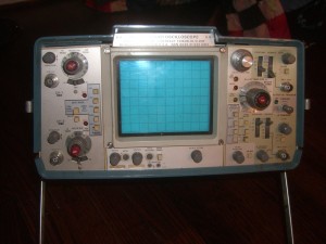
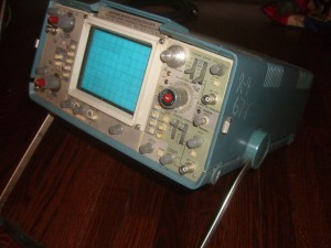
Tektronics 425M Oscilloscope:

A few months back I had mentioned how I blew up my Wurlitzer 200 and needed to start troubleshooting it for possible problems. I also lamented the fact that I didn’t have a scope to look at waveforms when I finally got the DC characteristic where I want them. Fast forward to a few weeks ago and a friend and co-worker mentions that he had a scope that he had purchased on eBay but was DOA. Apparently it broke in the midst of shipping and he didn’t get charged by the seller. He also bought a working scope later and intended to fix this one, but never got to it. As such he was clearing out room and offered it to me, a truly generous offer.

The scope itself is a dual channel, 100 MHz scope. It is a military version of the scope so it possibly has better spec’d parts (but I haven’t looked into this  too much).The main problem is that the beam does not render any images onto the phosphorescent screen. Other than that, it is supposed to work fine. Time will tell on the other components.

The interesting  thing about the older analog scopes is that many of them can be repaired by non-professionals. More accurately, they can be repaired by individuals not employed by Tektronics because the schematics are available, the components are large enough to replace quasi-easily and there aren’t proprietary ASICs you have to order from the OEM. One notable fixer-upper of all old things Tektronics is Jim Williams, applications engineer for Linear Technologies and electonics writer (my favorite thing about him is that he lists his 84 Tek scopes at home when he writes his own bios at the end of books or articles). All of these things lead to some analog engineers being die-hard fans of analog scopes. They also like that analog scopes never introduce sampling errors or glitches. This is less and less of a problem with new digital scopes on the market and yet the analog vs digital battle rages on (at least in my mind).

Oscilloscope

Oscilloscope

Goals/Projects:

  1. Get the front panel working
  2. Use it to troubleshoot any remaining hum and sound issues on the Wurlitzer 200
  3. Use it to aid me in creating a simple waveform generator (perhaps a buffered output from a computer?)
  4. Use it to troubleshoot issues that arise with the organ and other projects surrounding it

Hammond M3 Organ:

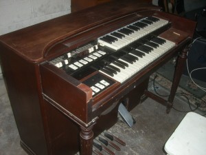
Another co-worker and I were discussing music one day and I mentioned my work on the Wurlitzer. He happened to mention how his wife would be very pleased if he would sell their organ; I was similarly pleased. I’ve been a fan of Hammond Organ in Soul Jazz and Jazz music (thanks Evan and Trevor) a while longer than I’ve been collecting the instruments used by them (thanks Noah).

The organ came to me in good shape sound wise; a little bit of hum but all of the keys are in really good shape and the drawbars work great. No Leslie speaker for now but the person who sold it to me says he might be able to sell me his model 900 eventually. I will also try and get one on my own in the mean time to see if I can’t get a better model (Model 122 or 145). The cosmetic condition of the organ is poor but I don’t think it would have as much character if the thing was squeaky clean. I also plan to possibly chop the organ at some point (put it into a smaller, transportable case) so the cosmetics don’t really matter.

Hammond M3 Organ Side

Hammond M3 Organ Front

Goals/Projects:

  1. Get the organ oiled and hum-less
  2. Successfully replace and re-bias the tubes on the main amplifier
  3. Build an external amplifier and cabinet to increase the sound output
  4. Create sound effect pedals to modify the sound output of the organ to my liking
  5. Document the internals of the tonewheel mechanism
  6. Chop the organ into a transportable case (less than the original weight of 250 lbs)

So these are some of my projects for the summer and possibly extending beyond into the rest of the year. I really look forward to working on two pieces of spectacularly engineered equipment. While I won’t be redesigning the equipment or doing much beyond touching up some of the worn out components, I hope to learn from the internals of these pieces of equipment and use them in future projects.

Do you have any ideas to build off of what I have listed here? What kind of projects are you working on this summer? Let me know in the comments!

Categories
Analog Electronics Digital Electronics Engineering

The Future of Troubleshooting

If you are an engineer who regularly works with your hands, you likely troubleshoot on a daily basis. It’s just part of the job. Sure, you can say, “I never mess up!”, but hardly anyone will believe you. Because even when your best laid plans go perfectly, Murphy’s Law will soon kick in to balance things out. We learn to deal with these things and have developed tools and measurement equipment to help us diagnose and deal with these problems: Multimeters, Electrometers, SourceMeters, Oscilloscopes, Network Analyzers, Logic Analyzers, Spectrum Analyzers, Semiconductor Test equipment (ha, guess I know a little about that stuff)…the list goes on and on. But what has struck me lately has been that as parts on printed circuit boards get smaller and smaller, troubleshooting is getting…well….more troubling.

  1. Package Types — I don’t want to get into another discussion of analog vs digital, but I will say that digital parts on average have many more pins which complicates things. And as the parts get more and more complex, they require more and more pins. The industry solution was to move to a Ball Grid Array package, using tiny solder balls on the bottom of the chip that then line up with a grid of similar sized holes on the board. When you heat up the part the solderballs melt and hold the chip into place and connects all of the signals. The problem is the size of the solderballs and the connecting vias: they’re tiny. Like super tiny. Like don’t try probing the signals without a microscope and some very small probes. But wait, it’s not just the digital parts! The analog parts are getting increasingly small to accommodate any of those now-smaller-but-still-considerably-bigger-than analog parts. You thought probing a digital signal was tough before? Now try measuring something that has more than 2 possible values!
  2. Board Layers — As the parts continue on their shrink cycle, the designers using these parts also want to place them closer together (why else would they want them so small?).The circuit board designers route signals down through the different layers of insulating material so that mutiple planes can be used to route isolated signals to different points on the board. So to actually route any signals to the multitude of pins available, more and more board layers are required as the parts get smaller and closer together. Granted, parts are still mounted on either the top or bottom of the board. But if a single signal is routed from underneath a BGA package, down through the fourth layer of an 8 layer board board and then up to another BGA package, the signal will be impossible to see and measure without ripping the board apart.
  3. High Clocks — As systems are required to go faster and faster, so are their clocks. Consumers are used to seeing CPU speeds in the GHz range and others using RF devices are used to seeing even higher, into the tens of GHz. The problem arises when considering troubleshooting these high speed components. If you have a 10 GHz digital signal and you expect the waveforms to be in any way square (as opposed to sinusoidal) you need to have spectral data up to the 5th harmonic. In this case, it means you need to see 50 GHz. However, as explained with analog to digital converters in the previous post, you need to sample at twice the highest frequency you are interested in to be able to properly see all of the data. 100 GHz! I’m not saying it’s impossible, just that the equipment required to make such a measurement is very pricey (imagine how much more complicated that piece of equipment must be). High speed introduces myriad issues when attempting to troubleshoot non-working products.
  4. Massive amounts of data — When working with high speed analog and digital systems there is a good amount of data available. The intelligent system designer will be storing data at some point in the system either for debugging and troubleshooting or for the actual product (as in an embedded system). When dealing with MBs and even GBs of data streaming out of sensors and into memories or out of memories and into PCs, there are a lot of places that can glitch and cause a system failure. With newer systems processing more and more data, it will become increasingly difficult to find out what is causing the error, when it happened and how to fix it.
  5. Less Pins Available out of Packages — Even though digital packages are including more and more pins as they get increasingly complex, often times the packages cannot provide enough spare pins to do troubleshooting on a design. As other system components that connect to the original chip also get more intricate (memories, peripherals, etc), they will require more and more connections. The end result is a more powerful device with a higher pin count, but not necessarily more pins available for you the user/developer to use when debugging a design.
  6. Rework — Over a long enough time period, the production of  printed circuit boards cannot be perfect.  The question is what to do with the product once you realize the board you just constructed doesn’t work. When parts were large DIP packages or better, socketed (drop in replacements), changing out individual components was not difficult. However, as the parts continue to shrink and boards become increasingly complex to accommodate the higher pin counts, replacing the entire board sometimes becomes the most viable troubleshooting action. Environmentally this is a very poor policy. As a business, this often seems to be a decent method (if the part cost is less expensive than the labor needed to try and replace tiny components) but if and when the failures stack up, the board replacement idea quickly turns sour.

While the future of troubleshooting looks more and more difficult, there have always been solutions and providers that have popped up with new tools to assist in diagnosing and fixing a problem. In fact, much of the test and measurement industry is built around the idea that boards, parts, chips, etc are going to have problems and that there should be tools and methods to quickly find the culprit. Let’s look at some of the methods and tools available to designers today:

  1. DfX — DfX is the idea of planning for failure modes at the design stage and trying to lessen the risk of those failures happening. If you are designing a soccer ball, you would consider manufacturability of that ball when designing it (making sure the materials used aren’t super difficult to mold into a soccer ball), you would consider testability (making sure you can inflate and try out the ball as soon as it comes off the production line) and you would consider reliability (making sure your customers don’t return deflated balls 6 months down the line that cannot be repaired and must immediately be replaced). All of these considerations are pertinent to electronics design and the upfront planning can help to solve many of the above listed problems:
    1. Manufacturability — Parts that are easy to put onto the board cuts down on problem boards and possibly allows for easier removal and rework in the event of a failure. It becomes a balancing act between utilitizing available space on the board and using chips that are easier to troubleshoot.
    2. Testability — Routing important signals to a test pad on the top of a board before a design goes to the board house allows for more visibility into what is actually happening within a system (as opposed to seeing the internal system’s effect on the top level pins and outputs).
    3. Reliability — In the event you are using parts that cannot easily removed and replaced and you are forced to replace entire boards, you want to make sure your board is less likely to fail. It will save your business money and will ensure customer satisfaction.
  2. Simulation — One of the best ways to avoid problems in a design is to simulate beforehand. Simulation can help to see how a design will react to different input, perform under stressful conditions (i.e. high temperature) and in general will help to avoid many of the issues that would require troubleshooting in first place. A warning that cannot be overstated though: simulation is no replacement for the real thing. No matter how many inputs your simulation has and how well your components are modeled, no simulation can perfectly match what will happen in the real world. If you are an analog designer, simulate in SPICE to get the large problems out of the way and to figure out how different inputs will affect your product. Afterward, construct a real test version of your board or circuit and make sure your model fits your real world version. By assuming something will go wrong with the product, you will be better prepared for when it does and will be able to fix it faster.
  3. Very very steady hands — Sometimes you have to accept the fact that you messed up and the signal traces on your board and you have to rewire it somehow. My analog chip designing friends needn’t worry about trying this…chips do not have the option for re-wiring without completely reworking the silicon pathways that build the chip. In the event you do mess up and have to try and wire a BGA part to a different part of the board or jumper 0201 resistors, make sure you have a skilled technician on hand or you have very steady hands yourself. And in the event you find yourself complaining about how small the job you have to do is, think of the work that Willard Wigan does…and stop complaining.
  4. On the Chip/Board tools — Digital devices have the benefit of being stopped and started at almost any point in a program (debug). Without being able to ascertain what the real world output values are though, it doesn’t help too much. If in the event you do not Design for Test and actually pull signals you need to probe to the top level then you create a board then there are a few other options. One option is to try and read your memory locations or your processor internals directly by communicating through a debugger interface. But if you are looking at a multitude of signals and want to see exactly how the output pins look when given a certain input there is another valuable tool known as “boundary scan”. The chip or processor will accept an interface command through a specified port and then serially shift the values of the pins back out to you. Anytime you ask the chip for the exact state of all the pins, an array of ones and zeros will return which you can then decode to see which signals and pins are high or low.
  5. Expensive equipment — As mentioned above when describing an RF system measurement needs, there will always be someone who is willing to sell you the equipment you need or work to create a new solution for you. They will just charge you a ton for it. In cases I have seen where a measurement is really difficult to calculate or you need to debug a very complicated system, the specially made measurement solutions often perform great where you need them, but are severely limited outside of their scope. To use the example from before, if you needed a 100GHz oscilloscope, it is likely whomever is making it for you will deliver a product that can measure 100GHz. But if you wanted that same scope to measure 1 GHz, it would do not perform as well because it had been optimized for your specific task. However, there are exceptions to this and certain pieces of equipment sometimes seem like they can do just about anything.

Debugging is part of the job for engineers. Until you become a perfect designer it is useful to have methods and equipment for quickly figuring out what went wrong in your design. Over time you become better at knowing which signals will be critical in a design and planning on looking at those first, thereby cutting down on the time it takes to debug a product. And as you get more experience you recognize common mistakes and are sure not to design those into the product in the first place.

Do you know of any troubleshooting tools or methods that I’ve missed? What kinds of troubleshooting do you do on a daily basis? Let me know in the comments!

Categories
Analog Electronics Digital Electronics Engineering

When To Use Analog Vs. Digital

Analog. Digital. Continuous. Discrete. Choices abound.

Well, not really.

In reality you will deal with both kinds of signals when working on just about any electronics these days. A simple example is in a switching regulator. These devices are meant to take input power from a wall plug or something providing a relatively constant voltage and then the regulator will ensure that the voltage is always the same when leaving. Internal to the circuit, a “digital” signal (on or off) determines when to let in incoming power go from the input to the output. The “digital” signal translates into an “analog” voltage at the output, hopefully the voltage you programmed.

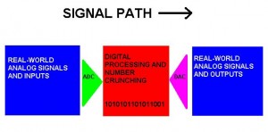
From there, systems become increasingly complicated, translating real world data to digital format, processing the digital data and spitting it back out again. The guts of the systems have infinite internal combinations and options, but in the end just about every hybrid system looks like this:

ad_system

The remainder of this post will be devoted to explaining situations that are either contained within the above system or situations that benefit from looking nothing like it; some of these situations mandate analog or digital implementation but more importantly, some are best implemented as analog or digital.

To start, what is the definition of analog? We’ll consider it a continuous signal that has infinite bandwidth and complete spectral information. Analog in the context of this site usually refers to the circuitry used to operate on those continuous signals, but we also use the word “analog” interchangeably to describe the signals. Which situations are best suited to using analog components and circuitry?

  1. Continuous filtering — Filtering a signal is necessary when it has frequency components included that you do not want. Some filters are digital and are extremely accurate at removing one signal while retaining others (FIR). However, if you are dealing with a continuous signal and you want to filter ALL possible frequency content (and not be limited by the sampling frequency you used when converting to digital), then you need a continuous analog filter. There are many options available that can also help to push your filtering towards accuracies similar to digital filters but they become increasingly complex (multi-pole active filters). The main advantage to an analog filter here is that it is simple, less expensive (usually) and beyond your roll-off frequency you know that all information is being removed (whereas it might still be hidden in a sampled signal).
  2. Pre-A/D and Post D/A — Hybrid systems require both analog-to-digital converters and digital-to-analog converters to switch between continuous and discrete data. However, the sampling frequency must be at least twice the frequency of the highest frequency component contained within the signal, as explained by Nyquist’s Theorem. In order to ensure that the Nyquist Theorem is fulfilled, you can filter (see above) any signals that are inadvertently included in the original signal so that it does not create noise and artifacts after sampling. Since the signal is not yet digital, you HAVE to filter the signal with an analog filter (convenient, right?). Once you are done operating on a signal digitally and you convert it back to analog, all processing must once again be done with analog components and circuitry (see picture above). I usually think of an iPod after the signal has gone through the DAC. You need to control the gain (volume) and shape the frequency components (tone). Some post DAC activities can be done in the processor, but are often more efficient (read: cheaper) to do in simple analog components after the DAC.
  3. High power — While digital measurement and control is possible for high power systems, having a digital signal that switches between 0 and 400V would not be efficient. In either AC or DC systems, analog components are responsible for transforming and transmitting signals (although there may be digital control of those analog components at some point in the system). The continuous nature of power delivery mandates analog components that are well characterized and durable.
  4. Gain Control/Signal Conditioning — Say you want to measure the amplitude of a 4000 V signal. You decide that you want to use a computer to do so, so you shove your signal into an A/D converter. But wait, where the heck do you find an A/D converter that can convert a 4000V signal? Sorry, they don’t exist (yet). You instead have to condition the signal to fit into a range of 0V to +2.5V, or whatever is the input range of your specific ADC. You can do so with a simple resistive divider (passive, simple) or an inverting amplifier (active, more difficult).
  5. Control systems — While digital control systems are possible and are becoming more and more prevalent, analog systems can be simpler. One of the simplest examples is an inverting op-amp configuration. The load of the op amp is the plant, the op amp is the controller and the resistors are the feedback paths to the summing node. There are some delays in the system, but in general, the signal can handle a wide range of frequencies without complicated circuitry and the system can adjust to however the input changes. In a similar digital system, the feedback resistor would be replaced with an ADC, some kind of computing machine (microcontroller) and a DAC to convert the data back to analog to push into the summing node. The system is dependent upon the technology and speed of the components, whereas the analog system is dependent on resistors and the nature of the load (plant). Digital control systems are becoming more popular as DACs and ADCs become faster and more accurate but as of now, analog control systems remain simpler in some of the more common instances.
  6. Sensors — These devices are meant to help convert real world information that isn’t necessarily electrical, into a format that is recognizable by a computer or embedded system. Oftentimes these are not taking real world (analog) data and directly turning them into digital signals. Instead, the sensor (sometimes known as a transducer) first creates an analog signal that can later be converted. Converse to the high voltage systems, sensors are often very low amplitude and require some signal conditioning to increase the value of the signal to better utilize the full range of an ADC.
  7. Fidelity/Data loss — Some people just love analog stuff, especially when it comes to music. Even though audio systems containing ADCs and DACs are making very good analog equivalents these days, you will have to tear the record players and the tube amps out of the hands of the most die hard audiophiles. So instead of converting back and forth between digital and analog media, they prefer to keep the signal continuous all the way throughout the process. Starting from the air pressure variations emitted from Louis Armstrong’s trumpet that are then captured by a microphone and then amplified and pressed into a record, then touched by a needle and amplified again by a transistor or tube amp to recreate the sound as it is pushed out of your high end speakers. And even though there are processes to mathematically capture all of the data that is present to sample and perfectly recreate the original signal, some people won’t touch the stuff. Since I can’t afford the high end equipment audiophiles claim is necessary, I will sit on the sidelines for this argument. However, I enjoy that there is still so much interest in preserving audio fidelity in analog formats and don’t mind that it keeps analog engineers employed.

I feel a little silly explaining digital advantages because they seem to be flaunted at every opportunity by media and digital chip makers. Still, let’s go over some of the more important places to use digital as opposed to analog.

  1. Computing — Again, I know it sounds silly, but digital has emerged as the better way to compute numbers. How did they compute mathematical sums before the advent of the microchip and digital logic? Why, operational amplifiers of course! That is actually where the name comes from, since there are many different possible operations for incoming signals.  If you have two incoming signals, one at 2 volts and the other at 1 volt, you can: add them (summing amplifier), subtract them (differential amplifier), integrate them or differentiate them. While this can and still does work quite well on a large signal DC basis, using operational amplifiers in the computing machines today would be a bit unruly. Just to start the power usage and the offsets would pose enough problems to make you run out and buy ADCs, DACs and micro-controllers. If you have a big math problem to do, follow that urge. However, if you do have a simple math operation you need to do on two signals and you don’t want the overhead of a digital section, op amps can still do the trick nicely; with their fast reaction and the complete lack of sampling issues you won’t miss those ones and zeros for a second.
  2. Counting — In analog systems, counting can be a difficult task. Instead, using integrators to “sum up” signals is a way to figure out where you might be in a process. Discretizing a signal and then counting how many times it happens can have many uses in control systems, measurement systems and a range of other applications.
  3. Memory — Storing analog signals would be difficult. For even a simple 0-1V signal, you would have to be able to store an infinite number of values. If you have 4 bits to represent the range from 0 to 1 volt, then you instead only need 16 places to store values. In control systems and other places that require memory, the old way to “store” values was to sufficiently delay them and feed them back so as to combine them with a newer signal. Using memory now allows for interesting systems and use of state machines to determine what to calculate or execute next based on current and past input data.
  4. High noise environments — If you are trying to transmit an analog walkie-talkie signal (5Vpp sine wave) in a field that happens to have a white noise generator transmitting (2V) at the same frequency you are using, it is likely that whoever is on the receiving end of that signal will also get a good bit of white noise in their signal (think static). If you instead use a digital signal (varying between 0 and 5V) your friend who has a digital transceiver will be able to discern your transmitted highs (5V) and lows (0V) even if they also have noise added to them. Once the digital data is received and decoded, the original signal (5Vpp sine wave) can be reconstructed on the receiving end.
  5. Signals Transmission – As stated above, there are advantages to transmitting digital signals as opposed to analog. Most notable is the lower power spectral density of the digital signals and that less power is needed to transmit those signals. In current events, we see TV transmission changing from analog to digitla because of the lower power required to transmit the signal and the possibility for multiplexing signals on specific frequencies in order to get more channels transmitted in the allowable spectrum.
  6. Data storage — To use the mp3 example again from above, data is best stored in a digital format (easy there audiophiles, records are alright for some people too). True, some information is lost, but only information above the Nyquist Sampling rate. In audio signals, most people cannot hear above 20 kHz, so there isn’t too much to worry about beyond that (perhaps the harmonics that some people claim to hear and desire in their recorded works).
  7. RF — Digital Signal Processing (or DSP) is one of my favorite digital topics. There are so many cool things you can do with a Radio Frequency (RF) signal once it is sampled and put into a powerful processor. In fact, this process makes your cell phones and Wi-Fi connections possible. FIR filters, CIC filters, baseband shifting and so many other interesting topics make it possible. Hell, maybe some day I’ll start “Chris Gammell’s DSP Life“. Anyway, can’t we do this stuff in analog? Well yes, we can. But with RF, it comes down to precision. With the filters listed above, you can trade off processor time/power for a more precise filter. In analog systems, you instead need more and more precise components and increasingly complex systems to achieve similar results. In DSP there is also reconfigurability, either through logic rework (FPGAs) or coding (in DSP chips), so long term investment usually will favor DSP over analog RF solutions. Finally, there is more efficient use of bandwidth with digital systems, so you can shove more data into the same frequency space. All of these things have helped to push the RF areas towards digital processing.

I think one of the most interesting things when reviewing this list is that it’s possible to implement solutions in myriad ways. Oftentimes cost and tradition (or past work) determine which way a solution will eventually lean (digital or analog). And although I hope to expand upon it in future posts the most interesting thing to me is that analog and digital begin to merge at the extremes: do analog signals really exist if energy is explainable by quantum mechanics? Will digital signal continue to only have two logical states when there is so much data storage capacity available between 0 and 1?

Please comment on the above lists–right or wrong–and let me know a situation or two that you think benefits from analog or digital.

Categories
Analog Electronics Music

Wurlitzer 200: Fixed

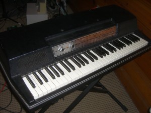
I am very excited to announce that the Wurlitzer 200 is fixed and operational. I say Wurlitzer 200 instead of 200A because a nice chap emailed me and let me know that I actually had an earlier model. Either way, it works and it sounds delicious.

Wurlitzer 200

Really this post is to gloat a little and to post the sound samples I recorded with my friend Joe. He is a great piano player and shows off the awesomeness of the Wurly better than I ever could. I also wanted to lay out some future posts about the Wurlitzer that I plan to write:

  1. Things learned about fixing the Wurlitzer. Schematics and my own drawings included.
  2. The importance of grounding for a clean signal and how it can affect other types of electronics.
  3. How transistors work and how the broken transistor on my Wurly was causing me grief.
  4. How fuses work and when to use them.
  5. Any others requested/suggested through the skribit box on the right.

Finally, here are the sound samples Joe and I put together today. It was fun recording again. For full disclosure, there was digital delay on the Wurly and there was some processing on the drums too. Also, I apologize that the drum tracks are a little loud; it’s because I’m an electrical engineer, not a sound engineer (and definitely not a professional musician). Enjoy!

Categories
Analog Electronics Learning Renewable Energy

Switching Regulators and Switching Noise

A background

Switching regulator, buck converter, boost converter, SEPIC, flyback, push-pull, buck-boost… do you know what the heck these things are??? Because I sure didn’t when I was getting back into analog electronics. Now thanks to new interest in power efficient electronics, they are starting to come front and center on the electronics stage. Hopefully this article will give you a better understanding of what they are, what they do, where to use them and issues with noise.

OK, so before we get to the real topic of this post, what do switching regulators do?

Switching  regulators allow you to translate one voltage into another. They allow you to take a higher voltage and translate it to a lower voltage or a lower voltage and go to a higher voltage.

“Eureka!” you cry, “Chris has found the solution to all of our energy needs! We just hook a bunch of these switching doo-dads up and we’ll have unlimited power!”

But no, it’s not that easy. Switching regulators go off the fact that you can take a voltage and translate it to a different voltage, however, the power stays the same (in an ideal case). Meaning if you have 5V coming into a circuit and you have a portion of that circuit that needs to operate off of a 15V supply, you can use a boost converter or something similar and crank up the voltage. Say you have 150 mA (at 5V) coming in, when you convert it up to 15 V, you’ll have 50 mA available to whatever needs the 15V power. Notice in this (ideal) case, the power stays the same (750 mW).

It is a similar story when going down  in voltage. However, there are many more options when moving down in voltage: switching regulator, linear regulator or even a passive element (like a resistor or a diode). You use a switching regulator because they regulate the output voltage (unlike the voltage drop across a resistor or a diode) and they don’t waste power like a linear regulator. If you want to go from a 20 V input down to a 5V output, a linear regulator would just “burn” up that 15V in the middle. With a switching regulator, most of the power is conserved (assuming you are running in the optimized voltage ranges…and there are a ton of different models to choose from so you can find the right range).

Finally, real quick, where are these used? Well, the hot new talk of the town has been renewable energy. “I can get 95% efficiency?” you ask, “Why wouldn’t I pay $4 per chip to do that?”. And really, the power efficiency isn’t just the garbage everyone seems to be spewing these days about saving energy for savings sake…it actually can help you make a better product. If you are in a heat sensitive situation, you don’t want to use a linear regulator to get your required voltage. In the above example if you are going from 100 mA at 20V and the output of the linear regulator is 100mA at 5V…that means you are burning 1.5W just regulating your voltages. With a switching regulator you can save a good percentage of that (for battery or “green” devices) and you can reduce the heat in a sensitive application. Plus, if you’re trying to go from a lower voltage to a higher voltage, you’re out of luck with linear regulators.

Switching Noise

Nothing in life is perfect. Switching regulators aren’t 100% efficient, there are limits to how much you can convert voltages (1000v down to 10V usually isn’t possible…or smart) and even in the best cases a switching regulator will introduce noise into a circuit. For the ways I have mostly used switching regulators (supplies for digital circuits), switching noise isn’t that big of a deal. If you are supplying 5V to a piece of flash memory, the part will probably not care if there is 100 mV of noise “on top” of the 5V signal (meaning the actual power supplied would bounce between 4.9V and 5.1V). Same for supplying power to LEDs or other non-analog situations. However, if there are any measurement components in your design or any even slightly sensitive analog portions, you should consider how the switching noise will affect your output.

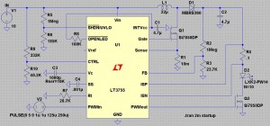
So why does switching noise occur? To answer that we really need to look at a switching regulator to understand what is inside of it. To illustrate, I will be using my version of LTSpice, which is free (awesome!). Also to note, there are lots of great programs out there to help you design this stuff (Webench, for example). Just don’t want to leave any of the vendors out, especially when they give out sampled parts. For this example, we’ll look at the LT3755, which EDN (and me by extension) showcased in an article about creating simple LED lighting for your home.  The application here would be to boost an input of 10V to an output of 40V to light an array of up to 14 1A LEDs.

lt3755

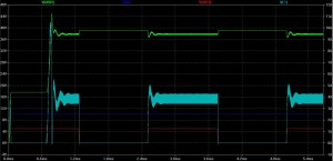
Notice the LEDs (D2 in the diagram) are where the final current and voltage is being delivered. The waveform for the inputs and outputs is below:

lt3755_chart_no_i

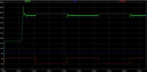
In this graph we see the voltage at the point above R4 (the sense resistor), which is close to what is being delivered to the LEDs. Notice that the voltage starts at roughly 15V and then shoots up to around 40V; the “on” state when the LEDs would be lit settles around 38V. When the red PWM waveform turns off, the voltage bounces up to the exact voltage (40V) the LT3755 is supposed to be outputting because the LEDs are not draining on the output of the circuit. When the PWM goes back on (to 5V), there is noticeable noise on the output voltage. So why is there noise?

lt3755_chart

If you look at the circuit diagram above, the second most critical component after the regulator itself is the inductor (L1), just to the upper right of the LT3755. Switchers take advantage of the fact that the voltage across an inductor is equal to the instantaneous current through an inductor times a constant (known as inductance). Pulsing current through the inductor introduces the voltages necessary to step the output voltage up to the desired level. Using negative feedback, the controlling chips can output pulses at varying speeds and shapes to correct for any errors on the output of the circuit (see the image above to see the current going through the inductor in light blue). However, as stated before, nothing is perfect. The bandwidth of the chip (the op-amps and other controlling elements within the chip) are finite, so there cannot be perfect control. This introduces noise on the output of the circuit at the same frequency as the switcher (and some harmonics of that frequency).  In the LT3755, the switching frequency can be anywhere from 100 kHz to 1 MHz.

If you are using this switcher for LEDs in a car…no big deal. And really, with high power applications such as lighting, the noise isn’t much of an issue. However, as switching regulators find their way into more and more products, the noise issue becomes more prevalent, especially smaller products. The trade-off comes in when you start looking at the inductor required for the switching regulator. Some can get quite large and unwieldy, especially for handheld products (see below for an unwieldy example).

So instead of using a large value (and size and price) inductor, the switching frequency needs to increase. As explained before, voltage is created across an inductor by forcing pulses of current through the inductor. The higher frequency means that there are smaller current pulses, but there are more of them. This allows for smaller and smaller inductors in designs (some are starting to be pulled into the chip packaging!) but brings with it the noise, now at a higher frequency.  If you have a 5V power supply line with 100 mV of noise of top of it (with the noise at around 100 kHz), then it might not be a problem on your circuit board. But when your boss tells you to start using smaller parts so you can fit the design in a handheld form factor and the switching frequency goes up to 1 and 2 MHz, you will start having problems. That innocent 100 mV from before now might couple into other board traces and introduce noise into the rest of your design. If you have any analog signals that are critical to your design, 100 mV of noise can wreak havoc on the output.

Less noise, more answers

Switching noise is something that will be apparent in any design involving a switching regulator. Knowing your system constraints will allow you to best decide which option is best for your specific needs. If you are crunched for space, you will need to be able to handle high frequency switching noise. If you are sensitive to noise, you better buck up for some big, expensive inductors and carefully route your board (in fact, if you’re that sensitive, maybe reconsider switching regulators entirely). If you have access to the resource, the best people to ask are the vendors selling the parts; they know the funny behavior of a part and which “flavor” of regulator to use to best suit your needs. And in the meantime you can play around with the tools they make available online and in software.

Please leave any questions or comments you might have and good luck with your new designs!