Categories
Analog Electronics Blogging Supply Chain

Why I love open source

There are so many great examples of open source these days. I find more and more that I can accomplish just about any task, either online or in the real world, with the aid of open source, especially software. For a relatively recent grad, I appreciate any opportunity to save money for the future. This could easily be the same case if I ever have the opportunity to start a business, as not many entrepreneurs relish the thought of paying thousands for an enterprise solution software package (such as Oracle). Let’s look at a few examples:

  1. Blogging – There are tons of sites out there that will give you space to host your blog either because they want exposure for their own site or have advertising motives. My blog is done published using WordPress, a wonderful free software. You can either have them host at their site or you can install their software really easily on your own hosting site. It’s amazing how well developed the software is and how easy it is to post and maintain online content. I remember when I first tried making websites back in the 90s I was so overwhelmed that I never ended up getting a site online. Now it’s a snap!
  2. Software – This is where the most open source opportunities come from and is really what drove the advances in open source. Here are some of my favorites.
    1. Wikipedia – This has to be one of the most prevalent examples on the internet today, not only of free software, but free information that is surprisingly accurate. The amazing thing about it is how effective it is as a standalone website. Google just about anything these days and a Wikipedia entry is likely to be at the top of the results. Why? Because Google works by popularity and whatever site the most people link to is usually the top hit on the results page (with some other criteria in there too). So many people link to Wiki articles though, that they often shoot to the top. Wikipedia is kept accurate and up to date by its contributors and moderated by some superusers, but has been shown to be effective as less and less people watch TV and instead spend their time online helping moderate content.
    2. Linux – A favorite of mine, this is the Windows killer that people have been talking about for years. It’s getting close, but Apple will probably chip away at Microsoft’s dominance first. Either way, it’s amazing how far the Linux systems have come from even just a few years ago. There are myriad releases available that suit different needs of users, but Ubuntu is the most popular now thanks to a user interface that is simple, similar to Windows and to be honest is spectacular. An add-on, once called Beryl, now Compiz-Fusion, is a spectacular interface that started following some of the OS X features (from Apple) and then was heavily copied in Microsoft’s Vista (flop). If you need some free software that does a tremendous job and is well supported, go with Ubuntu.
    3. PHP/MySQL – More software that makes this blog and many like it possible. WordPress is written in PHP, an open source software protocol that pulls from online databases. MySQL is the language that makes those databases possible. It is used in some of the most powerful sites on the web and is a simple standard to learn.
  3. Clothes – This one is definitely more unorthodox, but makes sense. A company called Threadless.com offers the opportunities to submit designs that are voted on by users and then they manufacture the most popular versions of the shirt and sell them. The artist gets a cut of the profits and the company doesn’t have to maintain an in-house staff. The situation is reminiscent of freelance photographers; it may not be the best for the artist, but it produces some spectacular work for the end user. Another company started doing this recently for shoes too. Soon you may be able to have an entire wardrobe based off of user created clothing!
  4. Music/Radio – Radio isn’t quite open source in the traditional sense, but online radio stations such as Pandora and Slacker are removing the need for big-wig dictated content. Allowing the user to decide what they will listen to more specifically than a station type with lots of songs you don’t want to hear (“104.8, playing hits from the 80s, 90s and today!). These online stations allow for you to pare down the specific genre you enjoy and then they will play songs from within that category
  5. Analog – This site is about analog, right? Well of course I’m going to include an example how this works.
    1. My favorite example is the open source tube amp project called AX84.com. Me and a friend built up an amp using the schematics and directions on this site; anyone is free to add their own variations and improvements to the base model to share with everyone. Some of the audio samples on the page show that these amps really can crank out some vintage, fuzzy tone that players the world over love.
    2. Another good example is the board layout from vendors. Often times a vendor will give an evaluation board in order to help sell a product (so the user can evaluate how well the product works before buying thousands of them). They will also offer the schematics of the eval board so that the user can directly copy it if necessary and save development time. Although the user does not usually share their modified end product, the fact that the board design can be re-used without a royalty payment makes it more “open” than “closed” source.

With all the free-ness of open source, why do companies do it? Why does anyone do it? Well, there still is an economically positive nature to open source. In the case of the clothing, Threadless.com still can make money through efficient production and distribution. They pass the cost of design to their submitters who make commission on their work. For the software companies, often times the open source version is available for companies to modify under the GNU public license (GPL) agreement, which says that if modifications are made that are not significantly different from the original that the changed version must be made available to the public. Sometimes when a company decides to deviate the software from the open source version, they decide to sell the new product and often times will offer professional support for the new version. Yet another way that open source providers can make money is through advertising revenues. A good example of this is Pandora, even though they are severely threatened by legislation that recently doubled the price of playing a song. Finally, sometimes, there is no revenue stream. People sometimes release open source information and products out of the goodness of their hearts or out of boredom.

Open source will continue to drive innovation because it allows for a free flowing of ideas. The fact that these ideas are free for all to use and modify and then share will ensure that more people will add to the collective knowledge and provide more open source products.
Categories
Analog Electronics Blogging Learning Life Supply Chain

A quarter century retrospective

When I started writing on my blog, I promised myself that it would not be about personal issues (“my roommate won’t pickup his socks!”) or rants about everyday happenings (“The people at the grocery store are slow!”). But I feel that reviewing the past 25 years of my life is good from a historical perspective and in terms of this blog so readers know more about where I’m coming from.

I am constantly amazed at how lucky I have been. I was born a white middle class male to loving parents and into a great family that encouraged my academic and intellectual achievement. I was also born in the United States of America, in an English speaking community that was voted one of the safest in America throughout my childhood. I’d say this already puts me in the top .1% of the world in terms of being dealt some great cards. Add to that the opportunities I’ve had with the school I was able to attend and the jobs I successfully interviewed for and I can’t think of many better situations. On top of all that, I work at a great company with lots of educational opportunities and I do something I really enjoy.

So not to sound like an Oscars speech, but I would like to thank so many people that made the past 25 years of my life possible. I want to thank my parents and sisters for being there for me and putting up with me. I’d like to thank all of my teachers throughout school that encouraged me, especially my high school physics teacher that inspired me to go into engineering. To all of my friends that are kind enough to click on my blog on a regular basis and give me great feedback on all things in my life, not just this blog. To our pound puppy Lola, who licks my face at every available chance and sits next to me whenever I need a canine friend. And saving the best for last, to my beautiful and brilliant girlfriend, who encourages me every day and loves me even when I’m writing about electronics and trying to explain it to her at 11pm.

That’s all for now. I thought one mushy post interspersed with serious posts wouldn’t be too bad, so I hope you enjoyed. Getting older always seems to have a stigma of life going faster and getting more hectic, but I think of it as more opportunities for learning and meeting new people. I’m sure this year will be another great one. If not, at least I can now rent cars with out that silly under-25 surcharge. Woo!

Categories
Analog Electronics Politics Renewable Energy Supply Chain

Solar Automation and Micro-Factories

I have a friend who alerted me to a company out in New Mexico known as Solar Automation. They don’t make solar panels; rather, they make the equipment to make solar panel arrays. However, what I find most intriguing about the company is their concept of Micro-Factories. In the case of Solar Automation, the basic idea is that a small team of people are capable of creating solar arrays by soldering the tiny wires with non-lead solder. This same concept could be expanded to many other applications, including mechanical or auto assembly, textiles, food preparation (already done at caterers, really).

Although it exists on a slightly larger scale, China epitomizes the Micro-Factory model. They have large labor pools using simple equipment to make incrementally more complex equipment. One example might be a board house that hand assembles and solders through-hole part boards. This could instead be done in a large facility with automation on expensive equipment. However, the cost for the equipment would likely mandate a large overall throughput for the factory in order to justify the cost of the equipment. Conversely, a smaller hand soldering operation could easily scale the number of people required to make an order of boards. As for energy savings, there can be higher efficiency with a laborer using a low wattage soldering iron as compared to heating lamps or continuously heating a wave solder machine.

The pivotal point in this argument is whether or not the end product requires increasing complexity in the machines that construct it. Solar is a good example. The panels themselves are not particularly complex, mostly they are tons and tons of PN junctions that convert incident light into flowing electrons. However, the chemicals and the semiconductor processing equipment is very complex.

So what are the benefits of Micro-Factories?

  1. Local workforce – With the exception of a privileged few (non-whiners), no one will contend that the US and the world economy is hitting some tough times. Local jobs are outsourced or cut outright. Mom and pop shop workers are now greeters at WalMart. Why not instead allow lower education workers have a job creating something useful for society and the environment, rather than peddling trinkets made 6000 miles away? Added bonus: Your workers do not have to travel from far away to work, thereby cutting down on costs and emissions.
  2. Simple training – Training is not cheap. If you ask people at Samsung, I was training for roughly a year and a half to do my job (and promptly left for a new one). It takes times to get into the swing of things at companies, no matter the task. Why not make the task simpler? The Solar Automation takes a complicated end process and allows simple training to quickly begin.
  3. Built in quality control (eyes) – While this would hinge on the enthusiasm of the workers (and therefore dependent on myriad other factors), it’s a fact that most computers do not notice something innately wrong with a process. Most people will notice if a solar panel is discolored or if a wire is hanging off where it’s supposed to be connected. Until the day when computers are smarter than humans (and cheaper), people will implement a natural form of quality control.

What are the drawbacks, you ask?

  1. If you give a mouse a cookie (cutter job), he’s going to want benefits – My own views about benefits and healthcare aside, it’s a fact that people expect some form of benefits, most easily represented in business as overhead. It expands beyond healthcare and such (think tables and chairs and other things that people expect from jobs), so you might have to label the job as “an alternative workplace” where compensation is higher (in the event you don’t want to/have to provide benefits). Doesn’t mean you can’t have a productive workplace though.
  2. In the solar example, there are still high material costs (the actual solar cells), so the margins will be squeezed. In general, assembly jobs are meant to be high volume, low margin endeavors, so there are risks when material costs rise; doubly so if your revenues are stagnant (because of contracts or otherwise).
  3. Sometimes it’s still cheaper to ship repetitive jobs overseas or automate a process. That’s all there is to it.

Micro-Factories could be a great way to increase employment, mobilize a stagnant workforce and help cut down on emmissions. I would highly suggest you check out the Solar Automation page and leave comments on other places you have seen similar ideas implemented.

Categories
Analog Electronics Politics Renewable Energy

Stealing stars and leaving the Barons in the dust

I recently had a high school friend visit and while watching the Olympics and having some beers, conversation turned to China (and the rest of the world). I know, I know, I’ve recently talked about the Olympics and China and such; But this is different. The conversation moved to energy and how it relates to national security, which I also have read about recently in a trade journal. Basically he brought up the astute point that renewable energy needs to be our number one priority in the coming years. We’re not talking 20 or 30 years…we’re talking 2 or 3. Really, it’s that important.

If you think about it, it makes perfect sense. Let’s say America reduces its energy dependence and busts its hump to get renewable energy contributing to say 40% of the country’s need (imagine a breakthrough that would allow this). What happens next? Well, if it was overnight (which it wouldn’t be), oil demand and prices would more than likely fall overnight too. Not to worry, I’m sure somewhere along the way that the demand would be filled by large countries that manufacture goods and want some newly cheap energy. But what about (the) US? In succession, we’d be able to say “Goodbye! No Thanks! Don’t Need it anymore!” to: Iraq…Iran….Russia….Venezuela….and China (though we probably wouldn’t with China, they make our stuff, right?). Almost all of the conflicts the US has with other countries center around oil! I would imagine it’s not going to stop with these countries either. Oil will become the driving force behind global conflicts for years to come, followed only by the fight for potable water. So why not go over the oil barons’ heads and make our own energy and let the wind and sun give us all the power for free?

40% of energy coming from renewable energy? Does the US have the brainpower to achieve that? No, not unless just about every scientist and engineer was capable of dropping what they’re doing and shift all their focus to working on energy. But there’s tons of smart scientists and engineers all over the world. What a break! In fact, there are engineers already doing a lot of this renewable energy work already. So maybe we could achieve two things here…first, the US would get scientists to help develop energy solutions that would allow us to ignore the tyrants of the world; second, the US would continue to maintain our most important resource going to the future: intellectual capital.

For the past 100 years, the US has been a leader in technology because of its innovators. These best and brightest minds created everything from electronic building blocks to the computers in which they were utilized. And now we’ve seen not only jobs going overseas, but a lot of the best minds are popping up outside this country too. Not only that, a lot of the top minds are coming to the US to study and then following jobs home to their native countries. So another solution for the benevolent (or otherwise) forces in the world: lure them to the United States and claim them as our own. While intellectual capital may have been one of our greatest resources that is arguably losing ground to the rest of the world, the US still has something that many other countries do not. What other countries have Hollywood, New York City, Chicago, LA, National parks bigger than certain countries and so on and so forth? Where do people want to move for jobs and stay and live and raise families? I think that the US needs to utilize the drawing power of our entire country, our availability of opportunities and our lifestyles (whether people agree with the decadence of western culture or not).

The future of the world in regards to energy is very uncertain; the US will remain a world power only if we are able to recruit the best minds, keep them here and have them help to create a world run on renewable energy.

Categories
Analog Electronics Learning

How an op amp works — Part 2

As promised, this post is a follow up post to explain the real-world behavior of an op amp. Here we will continue to anthropomorphize op amps in order to better understand their behavior and what they “want” to do. Also, we will look at some more complicated (but common) op amp configurations so that they are easily recognizable. Let’s begin.

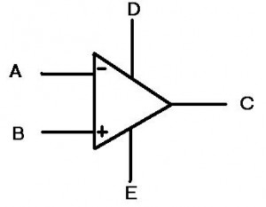
First, let’s look at the symbol for the op amp:

Whoa-ho! What the heck are those? Last time, there was only 3 lines coming out of the triangle and now there’s five! They’re multiplying!

Really the “D” and “E” inputs are the power inputs to the op amp. This means we are no longer simply dealing with the “ideal” case and are now going to look at the behavior with some realistic expectations. I know that when I was first learning about op amps, I was perplexed by this idea. I thought, “Well what is the point of putting power into an op amp? What do I get for it?” The idea is that as long as the signal at the input (or more accurately the difference between “A” and “B” is smaller than the power at the “D” and “E” terminals, then the op amp can amplify the signal. This gets very useful once you start encountering signals that change over time, or AC signals (as opposed to DC signals). Let’s look at this idea below:


Special thanks to CoolMath.com for the graphing program!

On the top left, we see a SINE wave, which is one of the simplest time varying signals there is. Amplifying this signal would not shift the signal, but instead would make the entire range of the signal larger. If we used a 4x amplification, then we would get the top right picture with the larger signal. Notice in the bottom picture the overlay of these two signals. They do not SHIFT up, but instead look like they are stretched. The easiest way to think of all this is at the extremes. If in the first picture the highest point was 1 and we had 4x amplification, then the output would be 4. However, the middle point is 0 and that multiplied by 4 is still zero. Hence the reason the overlay shows the extreme highs and lows being “stretched” the most. Also, it is important to note that these are analog signals, so EVERY point in between the extremes is being amplified.

The power coming into the op amp also restricts how much the op amp can amplify a signal. Not only that, but sometimes you don’t even get to go to the limits! Say you have +15 volts attached to “D” and -15 volts attached to “E” (most op amps have lower voltages these days but +/- 15 volts still happens sometimes). Now let’s say you have a 1V signal coming into a non-inverting amplifier (shown below). The gain on this amplifier is set to 15 by making the top resistor 14 times less than the resistor connected to the ground (non-inverting amplifiers have a gain of 1+R(top)/R(gnd)). So our 1 volt signal is placed at the non-inverting input (the plus) and the op amp says “15 volts, coming right up!”. Ah, but the op amp doesn’t quite have it. The op amp outputs 13.4 volts are so and then stops. “But WAIT!” you say, “why can’t this op amp output as much as I wanted? The ideal ones can output INFINITY. Can’t I just get one of those?” The short answer: no, you can’t. Op amps have internal protection circuitry that limits how high the input to the op amp can be in order to protect it from blowing up. Additionally, the op amp must consume some of that power in order to actually amplify the input signal; this will be expounded upon in further posts (the internals of an opamp).

The final point in this continuing discussion about op amps, is known as slew rate. Really it is a discussion of how fast an op amp can go and is limited by capacitance. Inside of any op amp, there is a capacitor, or rather a bunch of components that act together as one capacitor. This creates a required charge time for the internals of the circuit (for a more advanced look at this topic, check out the allaboutcircuits.com article on capacitors and calculus). The end result is that the op amp has some limit to how fast it can “decide” what the output should be. If we think back to the signals above that alter with time, we can imagine a situation where they would vary so quickly that an op amp would not be able to keep up. The end result is that a circuit such as the non-inverting amplifier shown above has some frequency above which it can no longer accurately amplify. This is known as the bandwidth of the circuit and has implications in many audio, measurement and communication industries.

This post discussed some of the real world aspects of op amps. The next post will discuss the internals of the op amp, such as the transistor setups. Imperfections in the silicon and the realities of material science will show us that more of the “ideal” op amp model is not possible in every day life; some potential topics are the input bias currents, the voltage offsets across the input terminals and how they can affect everyday circuits.

[xyz_lbx_default_code]

Categories
Analog Electronics Learning Music

Replacing capacitors on my Wurlitzer 200A electric piano

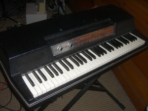
Things get old. Things eventually do not work anymore. Even the best engineers cannot design a system for part failures (unless they have triple redundant systems, like NASA). It is for this reason, I have decided to document on my blog the tune up of my Wurlitzer 200A electric piano (seen below) as opposed to the usual analog issues in the workplace today.

I mentioned this piano in my post about keeping it simple, namely not replacing EVERY component, only the ones that require an upgrade/replacement. It is a famous piano that can be heard in many types of music, spanning rock, soul, jazz and more.  Similar to the Fender Rhodes, the Wurly can be characterized by a darker, more over-driven sound and a built in vibrato (constructed from a simple oscillating circuit).

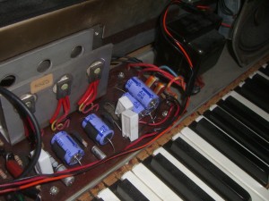
There are two components on these boards that need to be replaced the most often. The first is transistors, due to thermal stresses when they are over worked. In the case of my Wurly, the power transistors (seen below bolted to the large metal heat sink on the left) have started corroding, but have also had reduced output due to thermal stresses over the years. The board has upwards of 250 V and these transistors are ready to be replaced.

The other element that commonly needs to be replaced are the capacitors (the purple barrels seen above), specifically the electrolytic capacitors. An electrolytic capacitor is constructed by soaking paper in an electrolyte and sandwiching it between two aluminum plates (then attached to the leads of the capacitor). After about 10 years or so, the electrolyte begins to dry out and the capacitor degrades. Sometimes this can lead to a catastrophic breakdown (think “POP” or “BOOM”) or it can just mean that no signals will get through. Whereas I think of capacitors being frequency-dependent resistors (where the lower the frequency, the higher the resistance), these capacitors instead have resistance at ALL frequencies, due to the fact that the dielectric constant has gone from that of electrolyte to that of air. The final effect of all of this is a poorer sound, especially at the higher frequencies that are supposed to “pass through” a capacitor.

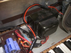
I am also hoping this will take care of some of the “hum” sound (most likely from 60 Hz); I’m hoping this will be resolved once the power filtering capacitors are replaced. I think that the ripple current may be higher since the capacitors have slowly degraded. This will impose the 60 Hz from the wall power onto the signal coming from the vibrating reeds (through the capacitive pickup). I also am wondering if the transformer (below) requires replacement, but I think I will replace the capacitors and transistors first.

That’s all for now, I will update more as I actually replace these capacitors. For now, enjoy the pictures and the sound samples (above links to Last.fm).

Categories
Analog Electronics Learning

How does an op amp work? How do I use an op amp? — Part 1

How does an op amp work? How do I use an op amp

These are questions that I have asked at two periods in my life. The first time was in my introductory circuits class and around that time I really didn’t care (beer was a priority). The second time was when I dove headfirst back into analog electronics for my new job and had to re-teach myself a lot of things. I really appreciate the opportunity I had to re-learn everything because the second time around, I think I got it right.

OK, so let’s start simple. What is an op amp? Whoa, loaded question. For our purposes here (and just for now), let’s say it’s just a symbol.

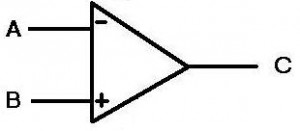
Figure 1: Just a symbol folks, nothing to see here

To keep things basic, the A & B points are the input, the C point is the output.This symbol is an IDEAL op-amp, meaning it is impossible to construct one and really the expectations for the op amp are unrealistic. But this is the internet and we can do what we want on the internet, so we’ll just use the IDEAL op-amp for now.

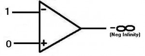
Figure 2: Inverting Ideal Op-amp

OK, so now you know what the symbol is, but what does it mean? Well, the idea is you put two electrical signals into the inputs then the output changes accordingly. It takes the difference between the inputs and amplifies it, hence operational amplifier, or op amp. You may have noticed that input A has a minus symbol and input B has a plus symbol. So let’s say that the input to the minus, or INVERTING, input is 1 (for simplicity’s sake…this site is about analog so that value could be ANYWHERE from 0 to 1 or higher! Just thought I’d mention that). The input to the plus, or NON-INVERTING, input is 0. Now the op-amp is in an unbalanced state. The device is designed so that when this happens, the output goes as negative as it can. For the ideal case, we say this is negative infinity, but that’s not really possible. More on that later.

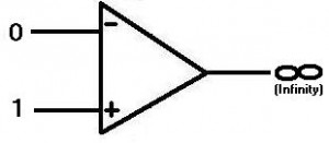
Figure 3: Non-inverting Ideal Op-amp

Conversely, in figure 3, if we put a one on the non-inverting and a zero on the inverting input, the op amp output would go high, infinity for our purposes here. The important thing to know is this:

The op-amp always “wants” both inputs (inverting and non-inverting) to be the same value. If they are not, the same value, the op amp output will go positive or negative, depending on which input is higher than the other.
(Throughout this article I will continue to anthropomorphize op amps…best to get used to it now)

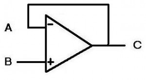
Alright, so how do we use this in circuits? If we wanted to find out if two signals were different, we could tie the signals to the inputs of the op amp, but then the output would go to infinity. This would not do us any good. The answer to this and many other questions in the universe is feedback. We are going to take the output and tie it back to the inverting input. Now the circuit looks like this:

Figure 4: A buffer
Figure 4: A buffer

First, we assume that the circuit has all points start at zero (point A being the most important). Next, we put a value of 1 (like the picture in figure 2) at the “B” non-inverting input. “WHOA,” says the op amp, “THIS AIN’T RIGHT!” So now the op amp puts its output to as high as it can, as fast as it can. This feeds back from the output (“C”) to the inverting input (“A”). So as the output moves closer to 1, the op amp is happier and backs off the output. When the input at A is the same as at B, the op amp is happy and stays there (but maintains the output of 1). The key here is that the op amp moves as fast as possible to get both inputs to be the same.

Why would someone use a buffer? Well that brings us to the next point about op amps, specifically ideal op amps:

Ideal op amps have infinite impedance (resistance) at their inputs. This means that no current will flow into the op amp.

A common use for a buffer is to supply current to another stage of a design, where the buffer acts as a gateway. So when the buffer “sees” a voltage at the input (“B”), it will output the voltage at “C”, but will also drive that voltage with current (as much as you want for an ideal op amp). This would be useful if you have a weak signal at the input, but want to let some other part of a circuit know about it. Perhaps you have a small sensor that is outputting a small voltage, but then you want to send the voltage over a long wire. The resistance in the wire will probably consume any current the sensor is outputting, so if you put that signal through a buffer, the buffer will supply the necessary current to get the signal to its destination (the other end of the wire).

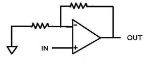
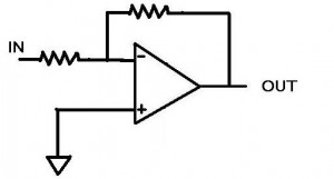
What if the signal coming from the sensor is too small though? What if we want to make it bigger? This is when we turn the op amp into an amplifier, using resistors. One of the more common ways of doing so is using the inverting input, shown below:

Figure 5: Inverting op-amp

Let’s go over what we know about this circuit. We know that the op amp wants both inputs to be the same. We also know that the non-inverting input is zero (because it’s connected to ground) and so the op amp will want the inverting input to be equal to zero (sometimes known as a “virtual ground”).  In fact, since the op amp has feedback through the top resistor (squiggly line if you didn’t know), then the (ideal) op amp will output just about any current and voltage in order to get the inverting input to be equal to zero.

So now our situation. A dashing young engineer hooks up a voltage source to the point “IN” set to 1 volt. This creates a voltage at the inverting input. “WHOA” says the op amp, and then it begins to output a voltage to make the inverting input point equal to zero. Since the input is 1 volt the op amp decides it better do the opposite in order to make the inverting input match the non-inverting input of zero. As fast as it can (infinitely fast for an ideal op amp), it outputs -1 volt. The inputs are both zero and everything is right in the op amp’s world. What about current though? We remember that current cannot flow into the op amp at the inverting input, so any current will be flowing through both resistors. If we have 1 volt at the input and a 1 ohm resistor at the input, then we will have 1 amp of current flowing (according to Ohm’s law V=IR). So when the op amp outputs -1 volt across the top resistor, there is a -1 amp going through it (assuming it is a 1 ohm resistor). The currents cancel each other out at the inverting input and the voltage then equals zero. The place where the currents meet is sometimes called the “summing node”. This is a useful representation when dealing with currents as opposed to voltages.

For the last part of this thought exercise, let’s look at a situation where the resistors at the input and at the top of the circuit are not the same. Similarly to above, the same dashing young engineer puts 1 volt at the “In” node. The resistor is still 1 ohm, so there is 1 A of current flowing through to the summing node. The op amp once again sees this 1 volt and once again says “WHOA, I’m unhappy about this” and starts outputting the highest voltage it can. However, in this situation, the top resistor is now 4 ohms. In order to create the -1 amp that is required to cancel the 1 amp going through the input resistor, the op amp must output -4 volts (remember V=IR).  We see that for an inverting op amp configuration, the ratio of the resistance of the top resistor to the bottom resistor determines the gain, or a multiplication factor from the input to the output. Also notice that the output is negative for a positive input, confirming that this is an inverting amplifier.

That’s the basics of it. Check back here for more about op amps, because there is a lot more to be said. Future posts might include other op amp configurations, design considerations and even the dreaded “REAL WORLD”, where the ideal op amp no longer exist.

[xyz_lbx_default_code]

Categories
Analog Electronics Music Renewable Energy Supply Chain

Keep it simple, stupid

Keep it simple, stupid

The KISS principle is pertinent in nearly every aspect of my life. I can’t begin to relay the number of times I have had to convince myself to step back from a situation–engineering or otherwise–and ask what the simplest solution is. Be it electronics at work or at home, renewable energy or even my investing, I encounter the KISS principle over and over again.

A tenet of the ever-expanding chip market is that the more functions that were once done with discrete components and can now be moved into the confines of a chip, the better. This is done either directly on silicon or by setting multiple pieces of silicon next to each other in the plastic packaging and wiring them together. This idea started a long time ago but is being to manifests itself in many different ways. One of the earliest examples is the op-amp. True, the form and function of the op-amp is different than the cascodes and the vacuum tubes that preceded it; but the idea of bringing the capacitor (to control the slew rate) and the transistors required to drive the differential inputs and the output all into the same package were just the first examples of combining discrete elements into an easily re-usable device was new. Another driving force was the idea that this device can be mass produced and sold at a lower cost thanks to economies of scale. More recently we have seen more and more functions brought into the chip packaging. One such example is the FPGA, which not only reduces the need for external logic gates in some bulky package, but it also makes it reconfigurable. And now, predictably enough, this same concept is being brought into play with analog! There are now chip manufacturers that make Field Programmable Analog Arrays (FPAA). Usually this consists of an op-amp, some analog switches and passive components, such as resistors and capacitors (for filtering). The device can be “programmed” to select any number of functions, with the potential for ever increasing complexity (though signal integrity would be a concern of mine). The final example is a product offering called the uModule from Linear Technology, with others doing similar things. It is an interesting concept because they are bringing in even more discrete components, such as inductors on a DC-DC converter; inductors are typically set outside the chip because of size concerns.

So how do these complicated chips affect designers and end users? They make things simpler (in theory). Open any modern day cell phone or look at a tear down, and you will see very little on the board in terms of discrete components (granted, this is also for space concerns). But chips that have everything included really do make everything simpler. Sometimes they are drop in solutions, such as with the uModule. All you need to do is determine the DC to DC conversion you want and then populate the board with their chip and two capacitors. On cell phones, there is usually 1 chip for each type of communication protocol (WiFi, CDMA, etc). If and when FPAAs ever become popular, they will only require that you populate a board with them, route the proper signals and then program what kind of filtering and amplification you want. This could even be as simple as saying what knee frequency you require and if you are particularly sensitive to ripple in the passband or stopband. Then the chip would know to use a butterworth, chebyshev, bessel, etc to get your desired results. The main point is, more and more people will be able to design systems, because the chip makers are paying attention to the minutiae (for a price, of course). This then allows fewer designers to make more designs, faster. Companies love the sound of that, because then they get more bang for their buck. As an aspiring futurist, I would even venture a guess that the system designers of tomorrow will really be software people with a knack for picking out parts. They will know what they need each part of the design to do and then will go through a catalog that will do it.

OK, so aside from using systems on a chip and not bothering to design systems when I can buy them, how else do I keep it simple? Well, a burgeoning hobby of mine is vintage analog electronics. Really I bought a 1968 Wurlitzer 200A electric piano on a whim and decided to fix it up/learn how to play it. The latter of those two goals is too lofty in the near term and shan’t be discussed here; however, the former of those goals has presented some good lessons from pulling this fine piece of equipment apart. When I first opened it and saw the components, I decided right away that I would  be redesigning everything, including a new circuit board and using the most efficient new parts. However, as I’ve dug into the design I’ve found that not only would this be silly, it could be detrimental. One of the best things about vintage audio electronics is the intangible “warm” sound they often have. This could be from using vacuum tubes or just noisy components that were designed to create the best sound they could at the time. If I replaced everything, I would lose the natural sound of the instrument, basically rendering it useless (in terms of re-sale and in terms of playability). Instead, the simplest course of action is to replace the dried out capacitors with the closest match I can and leaving everything else alone. Simplicity wins again!

Renewable energy, specifically solar, has begun taking the KISS principle to a new level. Solar panels are not yet cheap or abundant as we want and need them to be. But mirrors are! So why not take a really simple method of essentially putting mirrors on a parabolic dish and then pointing it at a water tower? This simple approach then forces the steam through a turbine and voila, electricity. Now create a project that does this many times over, in a desert no less, and you have a serious contender for long term energy independence.

“The best way to own common stocks is through an index fund.”–Warren Buffett…The best investor in the world and one of my personal heroes, says this about 99% of investors. Regardless of what this says about his confidence in the average (and not so average) investor, I think it is a perfect example of keeping it simple. In fact, it doesn’t really get much simpler. And history has proven it too. In 2006, a study found that only .6% of active money managers can beat the market. Keeping it simple and buying that index mutual fund will ease your mind and your wallet!

Do I follow these ideas in my life and work? Sometimes. But as I experience more and more, I find that the KISS principle is one that could bring more harmony into many different aspects of my life.

Categories
Analog Electronics Learning Work

My name is Chris…and I’m an analog engineer

Or am I?

I read technical publications on a pretty regular basis. And more and more lately, especially with the lull in the economy, I read about how jobs are going offshore or overseas. Sure, this concerns me, I’m human! Plus, I’ve inherited a worrisome nature from my mother. But I’ve had the fortune of reading a lot of articles about how analog engineers are in short supply. Even how they’re moving into green technologies!

Yahoo!” I think.

But wait a second, what’s all this.

I have read how analog engineers are hard to find. I know that the experience is both rare and valuable. But what kind of analog engineer I ask? Most of the articles I see are regarding silicon design and regardless of what I have done in the past with Samsung, I have never had the opportunity to look at analog design on silicon. And I have to wonder, am I allowed to call myself an analog engineer? I’m going to go with yes.

Here’s why:

  1. I know how to use an op amp
    • That’s one of those triangle things, right? I use these all the time and they are the basis of any analog engineer’s work. I feel like the main difference between myself and an engineer designing in silicon is I go out and buy a part for a dollar, they just go into a CAD library and plop one down in their design (and maybe mess around with it to get the specs they need). Anyone out there know if this is true or not?
  2. Yes, I even know how a transistor works
    • Granted, my silicon level knowledge is a little weak (I never liked calculating the number of electrons flowing through a PN junction…it just seemed so anti-Heisenburg). But plop an NPN transistor down in front of me (or a symbol of one), and I think I can fare pretty well. A great test of basic knowledge is in the chapter “A New Graduate’s Guide to the Analog Interview”. See how many of this limited passage you can get right.
  3. I know how to put it all together
    • There is a lot more to analog electrical engineering than knowing equations. A good example in my specific branch would be talking to vendors and getting pricing on parts. There are some big swings that can occur on prices of parts! Another example of putting it all together includes other aspects of design you might not think about. How about supporting a product 10 years down the line? I haven’t done this one personally (given my relatively short career thus far), but I’ve had to help out with some designs where the original designers were no longer around. And I’ll tell ya, some of those components were not meant to last! Needless to say, there is a lot of other tasks out there than just thinking up a circuit.

So even though I don’t intend on changing what I call myself anytime soon, I will clarify my skills. I am an analog system designer. Is that too far off? No, I don’t think so. Even the limited amount of design I’ve done really fits into that category. I have strung together a lot of components in order to create systems capable of processing analog signals. Further, sometimes the available system components (op-amps, buck/boost converters, etc) need to be made with passive components because of individual system constraints (meaning the stuff that vendors offer just don’t do what we need them to). I think more and more though, the industry will go towards system designers, simply because of rising costs. As systems get more and more complex, economies of scale mandate that people specialize in order to win business. We have also seen trends where chip makers are beginning to reach practical limits of how much better they can make certain devices (op amps, for instance). As such, we’ll see that the chip makers put more and more functions inside of chips.

So maybe one day I will work for a chip maker, trying to shove more components into a package? I enjoy the thought of creating a component that thousands if not millions would use. Perhaps this will be all that will be left to do? I’d obviously like to start learning it all before it’s the last frontier of design. Perhaps one day our tiny cell phones and other gadgetry will be nothing more than a screen and a single chip with every required function in it. But if I’m not making the screen or the chip, hopefully they’ll still need someone like me to hook that chip up to that screen. Who knows what the future will hold?

One final (and mostly unrelated) note I’ve been meaning to put in a post; writing about analog issues seems to be as good a time as any.  I’m sure at least one or two people noticed (probably not), I changed the tag line on my blog from “Chris Gammell’s Renewable Life” to “Chris Gammell’s Analog Life“. A few reasons: I think it makes more sense (I’m not Hindu, so I don’t really think life is “renewable” per se); the world around us is truly analog (as much as marketers would have us believe that music is “digital”); and to be blunt, I like the sound of it better.  Plus, I doubt too many people will be like “Wait, where is my favorite site??? Ohhhh, it just changed names…”.  This doesn’t mean I will stop looking at issues facing renewable energy, just that I want the focus of my site to be on analog.

That’s all for now. Chris Gammell, analog electrical engineer, out.

Categories
Analog Electronics Learning

Great resources for learning about analog electronics

I am absolutely floored by the internet every single day. I often wonder to myself if given the proper linking, guidance and mentoring, whether schools are even necessary any more (maybe the different methods are exactly what we need). This would of course also require some strong drive to learn and a whole lot of time on your hands, not to mention eyes that can bear reading computers screens all day. But I think it is possible; Some schools have even offered up their entire course catalogs online.

Me? I’m an information glutton. I will get 10 books from the library just because I get so excited about them, even if I only have time to read 2. As such, I thought I would clue everyone in to the absolute wealth of information on analog technology on the web. Most of the information you are going to find will be in the form of application notes (basically a cookbook on how to use a particular circuit). But sometimes you will find actual courses and training. I’ll be sure to list these first.  If you know of any other great resources, please leave them in the comments section! Enjoy!

National Semiconductor – The Analog University. Forget saving the best for last, this is by far the best resource I have found to date. There are full length courses that would make MIT blush.

Texas Instruments – This site has information on the entire spectrum of design from learning a concept, picking parts, creating the design and then simulating it.

Linear Technology (link 2) – These are app and design notes from one of the more robust companies out there.  There are also some great articles, some by none other than the great Jim Williams. See other work by Jim here.

Analog Devices (link 2) (link 3) – Analog devices is a monster supplier and has a lot of resources at their disposal. This allows for some great learning content. The links listed include the AnalogDialogue, a nice forum for analog discussion.

Here are some others with mostly app notes, but don’t discount them:

Maxim Semiconductor

ON Semi

Silicon Labs

NXP Semiconductor (formerly Philips Semiconductor)

That’s all I have for now in terms of online resources. I think I’ve maybe gone through about 2% of everything available, so I’ve got some reading to do!

On a side note, I’d like to welcome readers from the Motley Fool! Thanks for coming and feel free to take a look around!